English – KEYENCE SL-CHS Series User Manual
Page 34
Chapter 2 Installation and Assembly
2-12
2
English
ENGLISH
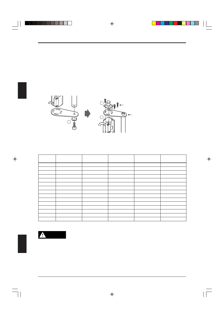
3. Tighten the bolt with the hexagon socket enough to hold them in place.
4. Tighten the bolts with the hexagon sockets with a mounting torque of 7 N•m while holding the
beveled area at the end of the bar (10 mm (0.39") diagonally) in place with a wrench.
5. Then use M3 (
r=7) screws to attach the bar brackets to the SL-CHS unit. Make sure the bar is not
skewed.
6. Use M3 (
r=10) screws with standard mounting brackets A, B, and C, as well as with L-shaped
mounting brackets.
7. Install 1 intermediate support bracket (included) onto protection bars when the bar length is longer
than that of OP-42357 (SL-CHS36H/SL-CHS18L). For information about how to install the
intermediate support bracket, see "2-8 E-to-E mounting bracket assembly and installation". For
information about the position at which the bracket should be installed,
see “1-4 Dimensional
Drawings (Dimensions by model) (page 1-7)”.
5
3
4
[Bottom]
[TOP]
* The bar should be secured
to the bottom in the same way.
Recommended tightening torque:
0.7 N•m
Recommended tightening torque:
7 N•m
* Non standard mounting bracket present or L-shaped mounting bracket: screw length is M3 (
r=7).
Standard mounting bracket present or L-shaped mounting bracket:
screw length is M3 (
r=10).
Number of required protection bar intermediate support brackets and E-to-E mounting brackets
Protection bar Applicable
Model
No. of Bar support
Intermediate
M3 (r=7) screw
M3 (r=10) screw
Model
to protection bar
brackets
support bracket
OP-42350
SL-C08HS
None
None
6
6
OP-42351
SL-C12HS
None
None
6
6
OP-42352
SL-C16HS
None
None
6
6
OP-42353
SL-C20HS
None
None
6
6
OP-42354
SL-C24HS
None
None
6
6
OP-42355
SL-C28HS
2
None
10
6
OP-42356
SL-C32HS
2
None
10
6
OP-42357
SL-C36HS
2
1
12
6
OP-42358
SL-C40HS
2
1
12
6
OP-42359
SL-C44HS
2
1
12
6
OP-42360
SL-C48HS
2
1
12
6
OP-42361
SL-C52HS
2
1
12
6
OP-42362
SL-C56HS
2
1
12
6
OP-42363
SL-C60HS
2
1
12
6
OP-42364
SL-C64HS
2
1
12
6
WARNING
When mounting the SL-CHS to a machine, use the mounting method shown in this
instruction manual, and make sure the SL-CHS is securely mounted.
Insufficiently tightened screws or incorrect mounting of the SL-CHS may cause a
serious accident, such as serious injury or death of the machine operator.
When mounting the models SL-C36HS through SL-C64HS or SL-C18L through SL-
C32L, be sure to use the intermediate support bracket provided with the accesso-
ries and mount it in the correct location for the SL-CHS Series.