Warning, Chapter 3 wiring, For npn output – KEYENCE SL-CHS Series User Manual
Page 41
Chapter 3 Wiring
3-5
3
ENGLISH
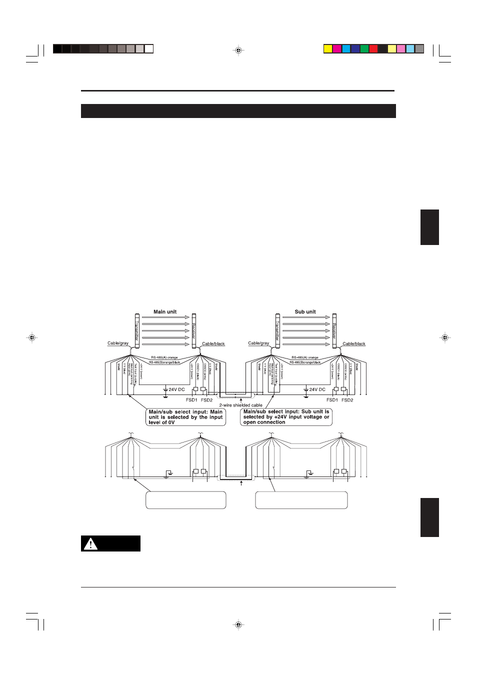
3-6 Connection for Light Interference Prevention (Parallel Connection)
As shown in the figure below, using the light interference prevention function allows the parallel con-
nection of 2 or more sets of the SL-CHS Series and prevents light interference in the respective the
unit of the SL-CHS Series. This connection method is called a light interference prevention connection.
(See the figure below.)
In this case, each of the parallel-connected SL-CHS units operates independently. Thus, when the beam
axis of one unit of the SL-CHS Series is blocked, its OSSD output (or FSD output) is turned OFF while
the OSSD outputs (or FSD output) of other unit of the SL-C Series connected in parallel remain ON.
To use the light interference prevention connection, first set a pair of units of the SL-CHS Series as the
main units. Also, connect the other unit of hte SL-CHS Series with the main units via light interference
prevention wires and set them as sub units.
Connect the main unit to the sub units using light interference prevention wires as shown below. The
connection sequence is as follows.
• Connect the main unit receiver's interference prevention cable (output/+) (gray) to the interference
prevention cable (input/+) (gray) sub unit transmitter that will be connected in parallel.
• Next, connect the interference prevention cable (output/-) (gray/black) of the main unit receiver to the
interference prevention cable (input/-) (gray/black) of the sub unit transmitter.
• Leave disconnected the interference prevention cable (input/+) (gray) and the interference preven-
tion cable (input/) (gray/black) for the unused main unit transmitters as well as the interference
prevention cable (output/+) (gray) and the interference prevention cable (output/-) (gray/black) for
the sub unit receiver after properly insulating them.
To enable the light interference prevention function, the power to the main units and sub units must be
turned ON. (If the power supply of a sub unit is turned OFF during the operation, said unit and its non-
priority sub unit will go into a lockout condition and their operations will be stopped.)
For PNP output
Light interference prevention
cable (input /-) (gray/black)
Light interference prevention
cable (output /+) (gray)
Light interference prevention
cable (input /+) (gray)
Light interference prevention
cable (output /-) (gray/black)
Light interference prevention
cable (output /+) (gray)
Light interference prevention
cable (input /+) (gray)
Light interference prevention
cable (output /-) (gray/black)
Light interference prevention
cable (input /-) (gray/black)
For NPN output
FSD1 FSD2
24V DC
Shield
Shield
Light interference prevention
cable (input /-) (gray/black)
Light interference prevention
cable (output /+) (gray)
Light interference prevention
cable (input /+) (gray)
Light interference prevention
cable (output /-) (gray/black)
0 V (blue)
0 V (Blue)
Main/sub switching
input (pink)
Test input (purple)
OSSD2 (white)
OSSD1 (black)
+24 V (brown)
+24 V (brown)
RS-485(B)orange/black
RS-485(A) orange
FSD1 FSD2
24V DC
Shield
Shield
Light interference prevention
cable (output /+) (gray)
Light interference prevention
cable (input /+) (gray)
Light interference prevention
cable (output /-) (gray/black)
0 V (blue)
0 V (Blue)
Main/sub switching
input (pink)
Test input (purple)
OSSD2 (white)
OSSD1 (black)
+24 V (brown)
+24 V (brown)
RS-485(B)orange/black
RS-485(A) orange
2-wire shielded cable
Light interference prevention
cable (input /-) (gray/black)
Main/sub select input: Sub unit is
selected by +24V input voltage or
open connection
Main/sub select input: Main
unit is selected by the input
level of 0V
This function is valid only when the number of SL-CHS connected in parallel via an light interference
prevention cable is 4 pairs or less and the number of SL-CHS Series beam axes is 192 or less. The
response time of each SL-CHS is not affected by the light interference prevention connection.
WARNING
Synchronization cables must be shielding cables. Failure to use the shielding cable
may result in significant harm to the machine operator, including serious injury or
death. Use 2-wire shielded cable that is at least AWG #22 (nominal cross-sectional
area of 0.3 mm
2
) for interference prevention connections. Also, use shielding that
has the same electric potential as that being used for the SL-CHS itself.
Otherwise, the SL-CH Series may not operate normally and serious harm such as
injury or death of the machine operator, may result.