English – KEYENCE SL-CHS Series User Manual
Page 13
Chapter 1 Overview and Specifications
1-5
1
ENGLISH
Common specifications
Environ-
mental
specifica-
tions
Material
Approved
standards
SL-C**HS Operating distance
Effective Aperture Angle
Response time
Light source
Operation form
Rating
Power voltage
Output type
Max. load current
OFF-state voltage
Protective structure
Ambient temperature
Storage ambient temperature
Relative humidity
Storage ambient humidity
Vibration
Shock
Main unit case
Upper case/Lower case
Overlay
EMC
EMS
EMI
Safety
OSSD
Output
Model
IP65 (IEC60529)
-10
°C to 55°C (No frost)
-10
°C to 60°C (No frost)
35 % to 85 %RH (No condensation)
35 % to 95 %
Ambient light
White incandescent lamp: 5,000
rx or less Sunlight: 20,000rx or less
10 to 55 Hz, 0.7 mm compound amplitude, 20 sweeps each in X, Y, and Z directions
100 m/s
2
(Approx. 10G) 16ms pulse, in X, Y, Z directions 1,000 times each axis
Aluminum
Zinc die-cast
Polycarbonate
UL61496-1
FCC Part15 Class A
UL61496-1 (
type
4 ESPE)
UL61496-2 (
type
4 AOPD)
UL508
0.3 to 9 m
Max.
±2.5° (When operating distance is 3 m (9.84 ft.) or more)
15 ms*
1
Infrared LED (850 nm)
Turns on when light is received from all light beams (except when the blanking function is used)
24V DC
±10% (Ripple P-P 10% or less)
2 outputs each for PNP and NPN, Can be changed using the connector cable
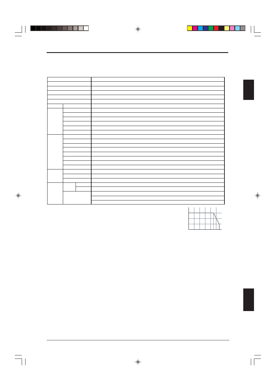
300 mA*
2
2.5 V (with a cable length of 7 m (22.97 ft.))
Max. 100
µA*
3
0.47
µF (with a load resistance of 100 Ω)
Max. 2.5
Ω*
4
SL-CHS Series
0
100
200
300
(mA)
10
20
30
40
50
(
°C)
Leakage current
Max. capacitive load
Load wiring resistance
*1 OFF
➝ ON return time is 125 ms.
*2 Note the derating illustrated in the graph to the right when using PNP output.
*3 Includes when the SL-CHS Series power supply is OFF or when there is a disconnection in the power
supply line.
*4 In order to guarantee the proper operation of the SL-CHS safety circuit, the wiring resistance
(excluding dedicated cable wiring resistance) of the cabling connected to the hardware to which the
OSSD output and OSSD input are connected must be 2.5
Ω or less. For NPN output type cable, do not
let wiring resistance exceed a maximum of 1.0
Ω when the cable length is 15 m (49.21 ft.) or greater
and the load current is 200 mA or higher.