English – KEYENCE SL-CHS Series User Manual
Page 24
Chapter 2 Installation and Assembly
2-2
2
English
ENGLISH
•
Correct mounting and installation
Install the SL-CHS away from hazards or hazardous zones to have the minimum safety distance that
has been defined by applicable regulations of the country or region where the SL-CHS is used.
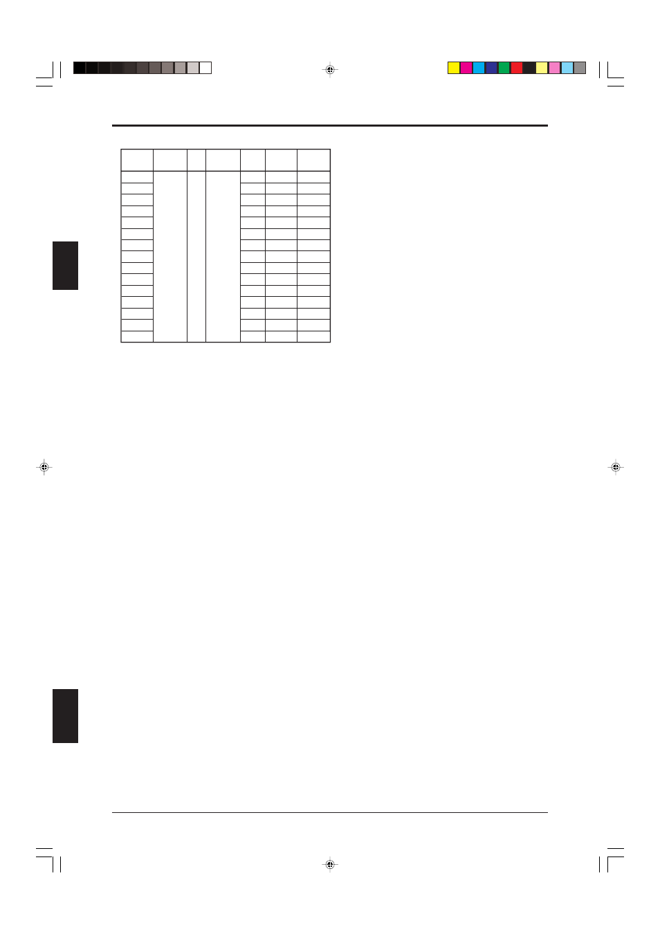
Model
Beam axis Beam Detection
Length
Detection Protection
interval
axis capability
zone
zone
SL-C08HS
150 (5.91") 140 (5.51")
185 (7.28")
SL-C12HS
230 (9.06") 220 (8.66")
265 (10.43")
SL-C16HS
310 (12.20") 300 (11.81")
345 (13.58")
SL-C20HS
390 (15.35") 380 (14.96")
425 (16.73")
SL-C24HS
470 (18.50") 460 (18.11")
505 (19.88")
SL-C28HS
550 (21.65") 540 (21.26")
585 (23.03")
SL-C32HS
630 (24.8") 620 (24.41")
665 (26.18")
SL-C36HS 20 (0.79")
Ш5
Ш25
710 (27.95") 700 (27.56")
745 (29.33")
SL-C40HS
(0.20")
(0.98")
790 (31.10") 780 (30.71")
825 (32.48")
SL-C44HS
870 (34.25") 860 (33.86")
905 (35.63")
SL-C48HS
950 (37.40") 940 (37.01")
985 (38.78")
SL-C52HS
1030 (40.55") 1020 (40.16") 1065 (41.93")
SL-C56HS
1110 (43.70") 1100(43.31") 1145 (45.08")
SL-C60HS
1190 (46.85") 1180 (46.46") 1225 (48.23")
SL-C64HS
1270 (50.00") 1260 (49.61") 1305 (51.38")
(Unit: mm)