KEYENCE DL-RS1A/IL User Manual
Page 8
6
Connecting the Unit to External Devices
Connection wiring
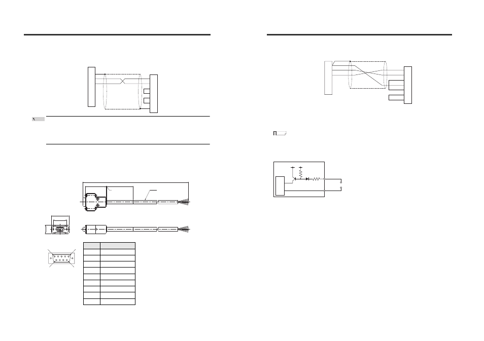
Refer to the connection wiring diagram shown below when connecting DL-RS1A to an external
device such as a PC.
• The length of the communication cable must not exceed 15 m.
• Connect the shield wire of the communication cable to the SG terminal of the external device.
• Make sure that the shield wire does not touch other signal wires or the other terminals on
the terminal block.
Optional cable
An optional cable shown below is used to connect to an external device such as a PC that has
a D-sub 9-pin I/O connector.
Part number: OP-81283
Pin layout for D-sub 9-pin connector
*1
Pin numbers 4 and 6 are connected inside the connector.
*2
Pin numbers 7 and 8 are connected inside the connector.
*3
Two cables (black and black/white) are connected to the pin number 5.
SD
RD
DR
ER
RS
CS
SG
2
1
3
4
5
6
RD
SG
SD
SG
SG
DRQ
DL-RS1A
External device
(D-sub 9-pin)
Shield
Point
Pin No.
Cable color
1
-
2
Red/white
3
Red
4
*1
-
5
Black, black/white
*3
6
*1
-
7
*2
-
8
*2
-
9
-
33.2
25
16
5000
39.5
1
50
φ7.1
Front
5
9
6
1
Connecting the Unit to External Devices
Sample wiring
*1
Insulate either the black or black/white cable that is not used.
*2
Connect the shield wire to the SG terminal of DL-RS1A. (Shield wire is connected to the
connector casing.)
The green and green/white-striped wires are not connected to any of the connector pins.
Input circuit diagram
*
The terminals for SG (Nos. 1, 4, and 5) are connected internally with the blue wire of the sensor
amplifier main unit.
2
3
4
5
6
7
RD
Red/White
Red
SD
DR
SG
ER
RS
8
CS
2
1
3
4
5
6
RD
SG
SD
SG
SG
DRQ
Black, Black/White*
1
DL-RS1A
(Communication terminal block)
External device
(D-sub 9-pin)
Shield
*
2
Reference
Main cir
cuit
(Short-circuit current: 1 mA max.)
6 (DRQ)
+5V
1,4,5 (SG)