KEYENCE DL-RS1A/IL User Manual
Page 15
13
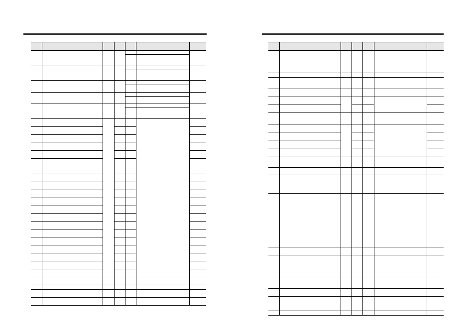
Parameters of Commands and Responses
024
Calculated value three-point calibration
SET2 Confirmation operation request
*5*12*13
*
1
R
0-1: Last written value
1
W
0
o1: Perform calculated value three-
point calibration 2nd point
request
*3
025
Calculated three-point calibration
SET3 Confirmation operation request
(Perform calculated three-point
calibration.)
*5*12*13
*
1
R
0-1: Last written value
1
W
0
o1: Perform calculated three-point
calibration 3rd point request
*3
026
One-point tuning request for diff. count filter
*
1
R
0-1: Last written value
1
W
One-point tuning request for diff. count
filter
*3
027
Two-point tuning
1st point confirmation operation request for
diff. count filter
*
1
R
0-1: Last written value
1
W
Two-point tuning for diff. count filter
*3
028
Two-point tuning
2nd point confirmation operation request for
diff. count filter
(Determine HIGH and LOW setting value.)
*
1
R
0-1: Last written value
1
W
Two-point tuning for diff. count filter
*3
065
HIGH setting value (BANK 0)
±**.***
(±***.**)
((±****.*))
7
R/W
-99.999 to +99.999
(-999.99 to +999.99)
((-9999.9 to +9999.9))
5.000 (+50.00)
((+500.0))
066
LOW setting value (BANK 0)
7
R/W
-5.000 (-50.00)
((-500.0))
067
Shift target value (BANK 0)
7
R/W
0.000 (0.00)
((0.0))
068
Analog output - upper limit value
(BANK 0)
*5 *6
7
R/W
10.000 (100.00)
((1000.0))
069
Analog output - lower limit value
(BANK 0)
*5 *6
7
R/W
-10.000 (-100.00)
((-1000.0))
070
HIGH setting value (BANK 1)
7
R/W
5.000 (50.00)
((500.0))
071
LOW setting value (BANK 1)
7
R/W
-5.000 (-50.00)
((-500.0))
072
Shift target value (BANK 1)
7
R/W
0.000 (0.00)
((0.0))
073
Analog output - upper limit value
(BANK 1)
*5 *6
7
R/W
10.000 (100.00)
((1000.0))
074
Analog output - lower limit value
(BANK 1)
*5 *6
7
R/W
-10.000 (-100.00)
((-1000.0))
075
HIGH setting value (BANK 2)
7
R/W
5.000 (50.00)
((500.0))
076
LOW setting value (BANK 2)
7
R/W
-5.000 (-50.00)
((-500.0))
077
Shift target value (BANK 2)
7
R/W
0.000 (0.00)
((0.0))
078
Analog output - upper limit value
(BANK 2)
*5 *6
7
R/W
10.000 (100.00)
((1000.0))
079
Analog output - lower limit value
(BANK 2)
*5 *6
7
R/W
-10.000 (-100.00)
((-1000.0))
080
HIGH setting value (BANK 3)
7
R/W
5.000 (50.00)
((500.0))
081
LOW setting value (BANK 3)
7
R/W
-5.000 (-50.00)
((-500.0))
082
Shift target value (BANK 3)
7
R/W
0.000 (0.00)
((0.0))
083
Analog output - upper limit value
(BANK 3)
*5 *6
7
R/W
10.000 (100.00)
((1000.0))
084
Analog output - lower limit value
(BANK 3)
*5 *6
7
R/W
-10.000 (-100.00)
((-1000.0))
097
Key lock function
*
1
R/W
0: Not key locked state
1: Key locked state
0
098
Bank function
*7
*
1
R/W
0 to 3
0
099
Timing input
*8
*
1
R/W
0: Timing input OFF
1: Timing input ON
0
100
Laser emission stop input
*8
*
1
R/W
0: Emission stop input OFF
1: Emission stop input ON
0
Data
number
Data name
Data
type
*1
Number of
characters
Attribute
*2
Readout range
*14
Initial
value
*14
Parameters of Commands and Responses
104
Sub display's screen
*
1
R/W
0: R.V. value screen
1: Analog value screen
2: HI setting value screen
3: LO setting value screen
4: Zero shift value screen
5: CALC value screen
0
105
System parameter settings
*9
**
2
R/W
0 to 15
0
106
Tolerance tuning - tolerance setting range
±**.***
(±***.**)
((±****.*))
7
R/W
-99.999 to +99.999
(-999.99 to +999.99)
((-9999.9 to +9999.9))
5.000 (50.00)
((500.0))
107
Calibration function
*
1
R/W
0: Initial state
1: User setting
0
108
Calibration function SET1
±**.***
(±***.**)
((±****.*))
7
R/W
-99.999 to +99.999
(-999.99 to +999.99)
((-9999.9 to +9999.9))
0.000 (0.00)
((0.0))
109
Calibration function SET2
7
R/W
5.000 (50.00)
((500.0))
110
Calculated value calibration function
*5
*
1
R/W
0: Initial settings
1: Calculated two-point calibration
2: Calculated three-point calibration
0
111
Calculated value two-point calibration
function SET1
*5
±**.***
(±***.**)
((±****.*))
7
R/W
-99.999 to +99.999
(-999.99 to +999.99)
((-9999.9 to +9999.9))
5.000 (50.00)
((500.0))
112
Calculated value two-point calibration
function SET2
*5
7
R/W
10.000 (100.00)
((1000.0))
113
Calculated value three-point calibration
function SET1
*5
7
R/W
5.000 (50.00)
((500.0))
114
Calculated value three-point calibration
function SET3
*5
7
R/W
10.000 (100.00)
((1000.0))
129
Calculation function
*5
*
1
R/W
0: OFF
1: Addition mode
2: Subtraction mode
0
131
Measurement direction
*
1
R/W
0: nor
1: rEv
0
132
Sampling cycle
*
1
R/W
0: Initial settings
1: 0.33 ms
2: 1 ms
3: 2 ms
4: 5 ms
0
133
Averaging/Diff. count filter/High-pass filter
**
2
R/W
0: 1 time
1: 2 times
2: 4 times
3: 8 times
4: 16 times
5: 32 times
6: 64 times
7: 128 times
8: 256 times
9: 512 times
10: 1024 times
11: 2048 times
12: 4096 times
13: Diff. count filter
14: High-pass filter
4
134
Output mode
*
1
R/W
0: N.O. (Normally open)
1: N.C. (Normally closed)
0
136
Hold function setting
*
1
R/W
0: Sample hold
1: Peak hold
2: Bottom hold
3: Peak-to-peak hold
4: Auto peak hold
5: Auto bottom hold
0
137
Auto peak hold or auto bottom hold trigger
level
±**.***
(±***.**)
((±****.*))
7
R/W
-99.999 to +99.999
(-999.99 to +999.99)
((-9999.9 to +9999.9))
1.000 (10.00)
((100.0))
138
Timing input setting
*
1
R/W
0: Level
1: Edge
0
139
Delay timer
*
1
R/W
0: OFF
1: Delay ON
2: Delay OFF
3: One-shot
0
140
Timer duration
****
4
R/W
5 to 9999
60
Data
number
Data name
Data
type
*1
Number of
characters
Attribute
*2
Readout range
*14
Initial
value
*14