KEYENCE DL-RS1A/IL User Manual
Page 13
11
Parameters of Commands and Responses
Data numbers
Specify the data number using three digits (ASCII characters).
z
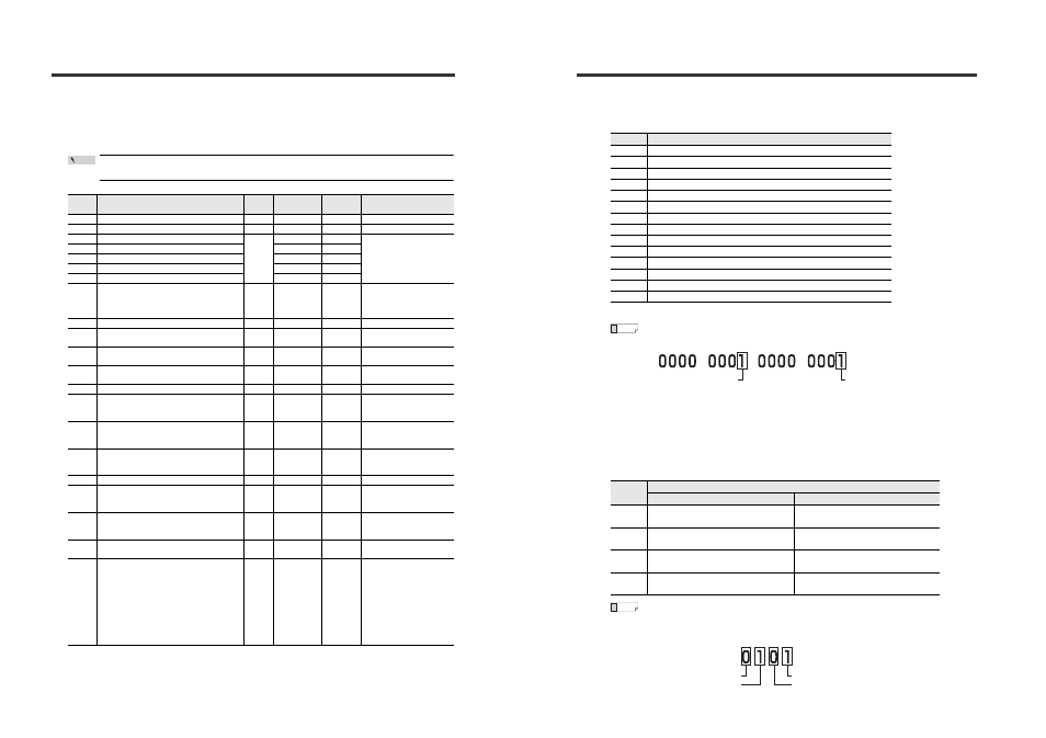
Read-only data
The following table lists the types of data that can only be read from the IL Series sensor amplifiers.
Writing read-only data results in a communication error (error number: 22).
*1
In the Data format column, "±" indicates that the value can be either "+" or "-" and "*" signifies a
number from "0 to 9". The values shown in parentheses apply for the IL-300/600, and the values
shown in double parentheses apply for the IL-2000.
*2
R: Indicates that the data type can only be read from the sensor amplifiers.
Data
number
Data name
Data
type
*1
Number of
characters
Attribute
*2
Readout range
*15
033
Sensor amplifier error
*3
*****
5
R
0 to 65535
036
Judgment output/Alarm output
*4
**
2
R
0 to 15
037
Judgment value (P.V. value)
*5
±**.***
(±***.**)
((±****.*))
7
R
-99.999 to +99.999
(-999.99 to +999.99)
((-9999.9 to +9999.9))
038
Internal measurement value (R.V. value)
*5
7
R
039
Peak hold value during hold period
*5
7
R
040
Bottom hold value during hold period
*5
7
R
041
Calculation value (CALC value)
*5 *6
7
R
042
Analog output value
*6
±*.***
or
**.**
Voltage output
6
Current output
5
5
Voltage output
-5.000 to +5.000
*7
Current output
04.00 to 20.00
*7
043
Bank status
*
1
R
0 to 3
044
Timing status
*
1
R
0: During sampling
1: Not during sampling
050
Laser emission stop state
*
1
R
0: Laser emitting
1: Laser stopped
051
Abnormal setting
*8
*
1
R
0: Normal setting
1: Abnormal setting
052
External input status
**
2
R
0 to 15
*14
053
EEPROM write result
*12
*
1
R
0: Executing
1: Normal termination
2: Execution impossible
054
Zero shift/Zero shift reset result
*9
*
1
R
0: Executing
1: Normal termination
2: Execution impossible
055
Reset request result
*
1
R
0: Executing
1: Normal termination
2: Execution impossible
056
Current system parameters
*13
**
2
R
0 to 15
060
Tolerance tuning/2 point tuning result
*10
*
1
R
0: Executing
1: Normal termination
2: Execution impossible
061
Calibration result
*11
*
1
R
0: Executing
1: Normal termination
2: Execution impossible
193
Product code
****
4
R
Main unit: 4022
Exp. units: 4023
195
Connected sensor head
****
4
R
0000: No connection
0001: IL-030
0002: IL-065
0003: IL-100
0004: IL-300
0005: IL-600
0106: IL-S025
0107: IL-S065
0208: IL-S100
0311: IL-2000
Point
Parameters of Commands and Responses
*3
You can read data number "033" to check the error status of the sensor amplifiers. Convert the
five digit number (ASCII characters) read from the sensor amplifiers to a binary number and
check the ON/OFF state of each bit to check the error.
For information on each error, refer to "IL Series User's Manual"
•
When the data read from a sensor amplifier is "00257":
"257" converted to binary number is "0000 0001 0000 0001".
Therefore, this data indicates that an "Overcurrent error" and a "Model mismatch
error" have simultaneously occurred at the sensor amplifier from which it was read.
•
If no error has occurred at the sensor amplifier, the data "00000" is returned.
*4
You can read data number "036" to check the judgment output status.
Convert the two digit number (ASCII characters) read from the sensor amplifiers to a binary
number and check the ON/OFF state of each bit to check the judgment output status.
When the data read from a sensor amplifier is "05":
"05" converted to binary number is "0101".
During N.O.
Bit
Sensor amplifier error details
0
Overcurrent error
1
EEPROM error
2
Sensor head error
3
Unused
4
Unused
5
Unused
6
Unused
7
Spot light laser error
8
Incompatable model error
9
Unused
10
Unused
11
Amplifier communication error
12
Number of units error
13
Calculation error
Bit
Judgment output
N.O.
N.C
0
0: HIGH Judgment output OFF,
1: HIGH judgment output ON
0: HIGH Judgment output ON,
1: HIGH judgment output OFF
1
0: LOW Judgment output OFF,
1: LOW Judgment output ON
0: LOW Judgment output ON,
1: LOW Judgment output OFF
2
0: GO Judgment output OFF,
1: GO Judgment output ON
0: GO Judgment output ON,
1: GO Judgment output OFF
3
0: Alarm output ON,
1: Alarm output OFF
0: Alarm output ON,
1: Alarm output OFF
Reference
Bit 8: Model mismatch error
Bit 0: Overcurrent error
Reference
Bit 3: Alarm output ON
Bit 0: HIGH judgment output ON
Bit 2: GO judgment output ON
Bit 1: LOW judgment output OFF