Reading – KEYENCE DL-RS1A/IL User Manual
Page 11
9
Commands and Responses
Reading
External devices such as PLC's use the following communication commands to read data from
DL-RS1A.
Read from the specified sensor amplifier (SR command)
Command
Response
Error response
Read all data from all sensor amplifiers (M0 command)
Command
Response
Error response
Read output states and data from all sensor amplifiers (MS command)
Command
Response
Error response
S
R
CR LF
ID No.
Data No.
,
,
S
R
Data*
1
ID No.
Data No.
,
,
,
CR LF
E
R
,
S
R
Error No.
,
CR LF
M
0
CR LF
M
0
CR LF
Data of the sensor
amplifier with ID:00*
2
,
Data of the sensor
amplifier with ID:01*
2
……
,
Data of the sensor amplifier
with the last ID No.*
2
,
,
E
R
CR LF
,
M
0
,
Error No.
M
S
CR LF
M
S
Control
output*
3
Control
output*
3
Control
output*
3
CR LF
Data of the sensor
amplifier with ID:00*
2
,
,
,
,
Data of the sensor
amplifier with ID:01*
2
…
Data of the sensor
amplifier with the last ID No.*
2
,
,
Sensor amplifier with ID:00
Sensor amplifier with ID:01
Sensor amplifier with the last ID No.
E
R
CR LF
,
M
S
,
Error No.
Commands and Responses
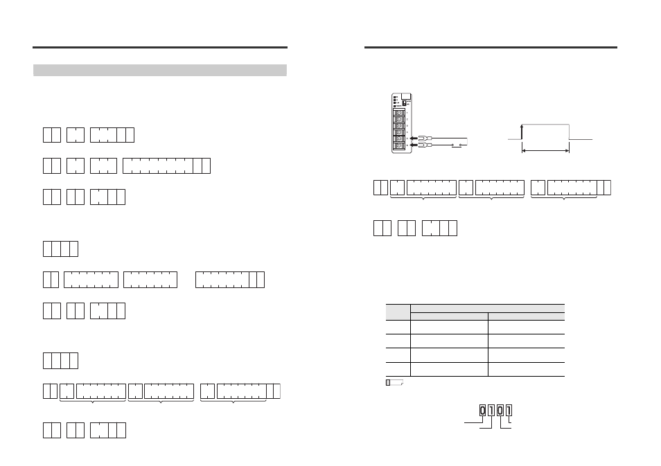
Read with external input to the DRQ terminal (DRQ read)
You can send an input signal (by short-circuiting DRQ (terminal number 6) and SG (terminal number
1, 4, or 5)) from an external device such as a PLC instead of sending a command.
Response
Error response
*1
The data length is different depending on the data being read. (Up to 10 characters)
*2
For IL-S025/IL-030/IL-S065/IL-065/IL-S100/IL-100: ±**.*** (reading range is -99.999 to +99.999)
For IL-300/600:
±***.** (reading range is -999.99 to +999.99)
For IL-2000:
±****.* (reading range is -9999.9 to +9999.9)
*3
Data length: 2 characters
On the IL Series, the judgment output (HIGH/LOW/GO output) and the alarm output ON/OFF are
displayed with 2-digit number (ASCII characters). Convert the 2-digit number (ASCII
characters) read to a binary number and check the ON/OF status of each bit to check the
judgment output status.
•
When the read data is "05":
"05" is converted to the binary number "0101".
When N.O.
Bit
Judgment output
When N.O.
When N.C.
0
0: HIGH judgment output OFF,
1: HIGH judgment output ON
0: HIGH judgment output ON,
1: HIGH judgment output OFF
1
0: LOW judgment output OFF,
1: LOW judgment output ON
0: LOW judgment output ON,
1: LOW judgment output OFF
2
0: GO judgment output OFF,
1: GO judgment output ON
0: GO judgment output ON,
1: GO judgment output OFF
3
0: Alarm output ON,
1: Alarm output OFF
0: Alarm output ON,
1: Alarm output OFF
2 ms min.
Input signal
ON
OFF
SG
RD
SD
SG
SG
DRQ
D
R
CR LF
Data of the sensor
amplifier with ID:00*
2
,
,
,
,
Data of the sensor
amplifier with ID:01*
2
…
Data of the sensor
amplifier with the last ID No.*
2
,
,
Sensor amplifier with ID:00
Sensor amplifier with ID:01
Sensor amplifier with the last ID No.
Control
output*
3
Control
output*
3
Control
output*
3
E
R
CR LF
,
D
R
,
Error No.
Reference
Bit 3: Alarm output ON
Bit 0: HIGH judgment output ON
Bit 2: GO judgment output ON
Bit 1: LOW judgment output OFF