Other settings, Zero point positioning, Bank switching – KEYENCE IA Series User Manual
Page 4: Keylock function, Initial reset (initialization), Custom save (saving the settings), Custom reset (loading the settings)
4
IA Series-IM_E
z Current value and display resolution
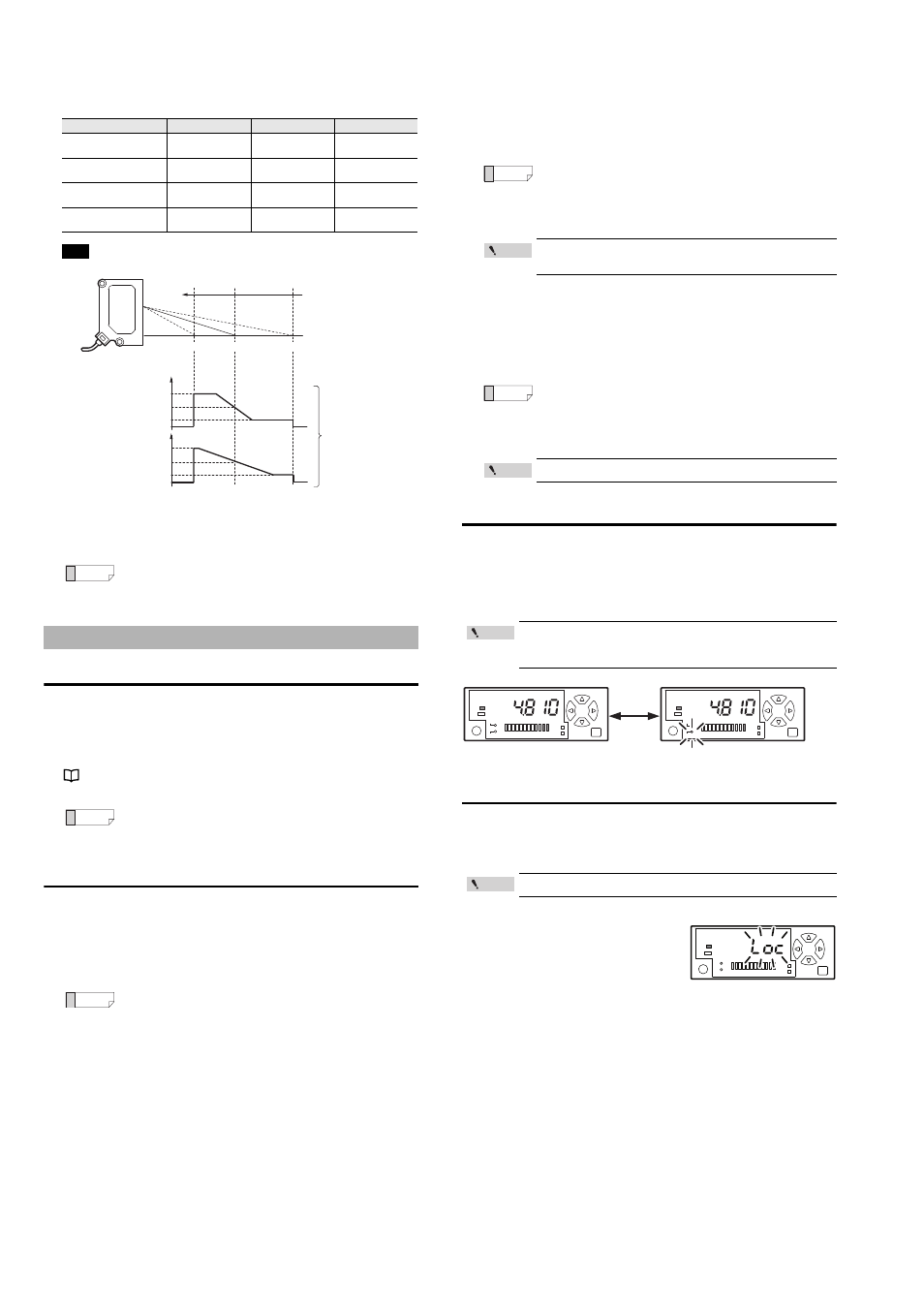
By default, the current value is displayed as 0 when the workpiece is located at the
reference distance from the detection surface of each head. Bringing the workpiece
closer to the sensor head gradually increases the value and taking it farther gradually
decreases the value.
When using sensor head IA-030
z Peak/bottom values
The peak and bottom values are indicated as they are recorded after either the
power is turned on or the held value is reset.
Zero point positioning
Sets the current value to zero.
1
Press the [Up] and [Down] arrow buttons simultaneously without a
workpiece in place.
Or, select "Zero shift input" in "4. External input function setting", and input the
external input.
"4. External input setting" (page 5)
The current value becomes "0" and zero point positioning is complete.
Initial reset (initialization) and custom save function
Initial reset (initialization)
Returns all of the settings to the factory defaults.
1
While pressing the [MODE] button, press the [SET] button five times.
2
Press the [Down] arrow button to display "
rSt no".
3
Press the [Up] or [Down] arrow button to select "
rSt ini", and then
press the [MODE] button to initialize.
■
Custom save (Saving the settings)
Saves all of the settings. The saved settings can be loaded at a later time.
1
While pressing the [MODE] button, press the [SET] button five times.
2
Press the [Left] or [Right] arrow button to display "
SAv".
3
Press the [Down] arrow button to display "
SAv no".
4
Press the [Up] or [Down] arrow button to select "
Sav YES", and then
press the [MODE] button to save the settings.
■
Custom reset (Loading the settings)
Loads the settings saved with custom save.
1
While pressing the [MODE] button, press the [SET] button five times.
2
Press the [Down] arrow button to display "
rSt no".
3
Press the [Up] or [Down] arrow button to select "
rSt CSt", and then
press the [MODE] button to load the settings.
Bank switching
The bank function allows two patterns of analog range settings to be saved in bank A
and bank B. (This is useful during operations such as switching the setup.)
•
The bank switching function can only be used when the input is set to "
bnk" in the
settings.
•
The banks are switched with external input.
Keylock Function
The keylock function prevents accidental operation of the buttons during detection.
While using the keylock function, operations other than switching the display for the
main screen are prohibited.
Setting/releasing keylock
While pressing the [MODE] button in the main
screen, press and hold the [UP] or [Down]
button for at least three seconds.
This sets (or releases) keylock and returns the
sensor to the main screen.
Item
IA-030
IA-065
IA-100
Reference distance
(mm)
30
65
100
Measurement distance
(mm)
20 to 45
55 to 105
75 to 130
Digital display
(Default value)
10.000 to
-15.000
10.000 to
-40.000
25.000 to
-30.000
Display resolution
(
μm)
1
2
2
The held peak and bottom values can be cleared by pressing and
hold the [Up] arrow button.
Other Settings
Pressing the [Up] and [Down] arrow buttons simultaneously for at
least three seconds cancels the zero point.
When "
rSt no" is displayed, pressing the [MODE] button returns
to the main screen without initializing.
Example
Measurement distance (mm)
* For the details, see "5. Analog output scaling (bank A/B)" on page 6.
Bank A
Bank B
analog voltage
output
0.5V
0.2V
2.25V
4V
Zero point
(changeable)
10.500
0
-15.500
Current value of the
amplifier unit (mm)
30
19.5
IA-030
0.5V
0.2V
2.25V
4V
The bank switching
function can be used
to switch between two
patterns for the range.
45.5
Reference
Reference
Reference
When "
SAv no" is displayed, pressing the [MODE] button returns
to the main screen without saving the settings.
Performing custom save overwrites the settings from the
previous custom save.
When "
rSt no" is displayed, pressing the [MODE] button returns
to the main screen without performing custom reset.
Performing custom reset erases the current settings.
When the external input is off, bank A is used. When the external
input is on, bank B is used. (Keylock is not needed)
The banks cannot be switched by operating the buttons.
The keylock settings can only be set in the main screen.
Reference
Point
Reference
Point
Point
SET
MODE
MODE
BANK
CENTER
BANK
CENTER
SET
Bank A is in use : Bank indicator is off
Bank B is in use : Bank indicator is on
Point
During keylock
DATUM
SET
MODE