Precautions on regulations and standards, Checking the package contents, Mounting and wiring the sensor amplifier – KEYENCE IA Series User Manual
Page 2: Mounting the sensor amplifier, Amplifier wiring, Ce marking, Ul certificate, Sensor amplifier sensor head, Mounting the ia-1000, Series
2
IA Series-IM_E
CE Marking
Keyence Corporation has confirmed that this product complies with the essential
requirements of the applicable EC Directive, based on the following
specifications.
Be sure to consider the following specifications when using this product in the
Member State of European Union.
z EMC Directive(2004/108/EC)
•
Applicable standard EMI : EN61326-1, Class A
EMS : EN61326-1
•
The length of cable connected to the power supply connector must be less
than or equal to 30m.
•
For the Analog voltage output cable, adopt two ferrite cores under following
conditions.
Location
: 200 mm or less from the end of Analog voltage output cable.
Ferrite core : ZCAT2035-0930, Manufactured by TDK (5 turns)
SFT36SN, Manufactured by TKK (2 turns)
Remarks:
These specifications do not give any guarantee that the end-product with this
product incorporated complies with the essential requirements of EMC Directive.
The manufacturer of the end-product is solely responsible for the compliance on
the end-product itself according to EMC Directive.
UL Certificate
This product is an UL/cUL Recognized component.
•
UL File No. E301717
•
Category NRKH2, NRKH8
Be sure to consider the following specifications when using this product as an
UL/cUL recognized component.
•
Use the power supply with Class 2 output defined in NFPA70 (NEC: National
Electrical Code).
•
Power supply, Control input and Analog voltage output circuits shall be
connected to a single Class2 source only.
•
Use with over current protection device which is rated 30V or more and not
more than 1A.
Check if the parts and equipment listed below are included in the package of the
model you purchased before using the unit.
Sensor amplifier
Sensor head
We have thoroughly inspected the package contents before shipment. However,
in the event of defective or broken items, contact your nearest KEYENCE office.
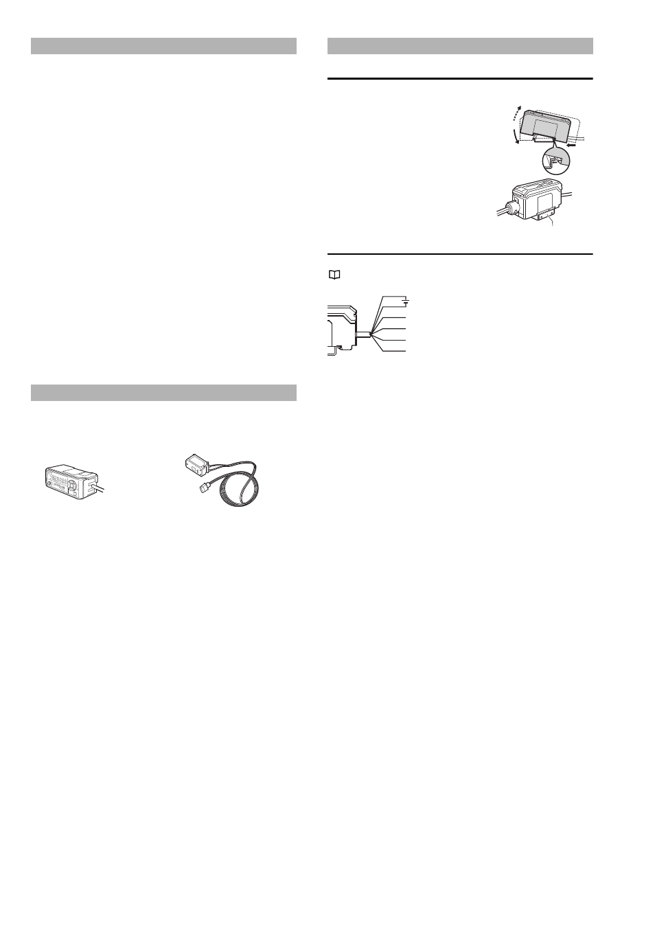
Mounting the sensor amplifier
Mounting the IA-1000
1
Align the claw at the bottom of the
main body with the DIN rail. While
pushing the main body in the
direction of the arrow 1, slant it in the
direction of the arrow 2.
2
To dismount the sensor, raise the
main body in the direction of the
arrow 3 while pushing the main body
in the direction of the arrow 1.
When using the amplifier mounting bracket
(OP-76877) (sold separately), mount it as
shown in the diagram to the right.
Amplifier wiring
The following information shows the I/O cable.
"I/O Circuit Diagram" (page 6)
* The external input switches as shown below
depending on the amplifier settings.
•
bnK .......... Bank switching
•
SFt .......... Zero shift
•
oFF .......... Input off
Precautions on Regulations and Standards
Checking the Package Contents
series
IA
z IA-1000
Amplifier
x1
Instruction manual x1
z IA-030/065/100
Sensor head
x1
Mounting bracket
x1
Insulating sheet
x1
Flat nut
x1
M3 x L30 screw
x2
Laser warning sticker*
x1
* This is not included with IA-030.
Mounting and Wiring the Sensor Amplifier
1
3
2
Amplifier mounting bracket
Analog voltage output
(0.5 to 4 V)
Brown
Blue
Black
Shielded
Pink
*
Purple
Analog voltage output
(GND)
External input
Laser emission
stop input
10 to 30 VDC