Lv-s31, Adjusting the trimmer (detection position), Adjusting the detection center – KEYENCE LV-N10 Series User Manual
Page 4: Lv-s41/s41l, Lv-s62, L-mounting bracket (optional: op-84350), Back surface mounting bracket (optional: op-84349), Horizontal mounting bracket (optional:op-84351), Lv-s71/s72
4
LV-S31
Adjusting the trimmer (detection position)
The detection range can be selected freely by adjusting the trimmer.
Adjusting the detection center
1
Place a workpiece at the position to be set as the detection
center.
2
Turn the trimmer and adjust so that the (2) JUST (center) indicator lights in green.
To set in further detail, adjust while monitoring the amplifier display. (Page 7)
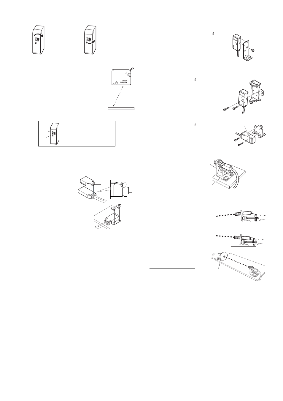
LV-S41/S41L
Always use the included mounting bracket.
1
Attach the mounting bracket as
shown on the right.
Match section A of the bracket onto
section B of the sensor head.
2
Attach onto a flat surface with M3
screws as shown on the right.
(M3 screws are not included.)
LV-S62
Mount with the optional L-mounting bracket (OP-84350), back surface mounting bracket (OP-
84349) or horizontal mounting bracket (OP-84351).
L-mounting bracket (optional: OP-84350)
Included: Mounting bracket
1 / plate nut
1 / M3
7.3
screw
1
Back surface mounting bracket (optional: OP-84349)
Included: Mounting bracket
1 / M3
18
screw
2
Horizontal mounting bracket (optional:OP-84351)
Included: Mounting bracket
1 / M3
18
screw
2
LV-S71/S72
1
Attach so that the side on
which the T (transmitter) and
R (receiver) are printed faces
upward. The operation indica-
tor lights are on the printed
side.
2
Adjust the beam axis.
The beam axis can be adjusted in the downward
direction by tightening the screw as shown with the
arrow. It can be adjusted in the upward direction by
loosening the same screw.
Adjust so that the beam spot is centered on the
receiver.
When adjusting, attach the beam axis alignment
plate included with the sensor head onto the end
of the receiver side to aid in alignment.
Remove the beam axis alignment plate when fin-
ished adjusting.
F
J
N
F
N
F
J
N
F
N
To detect from a long
distance, turn the
trimmer clockwise
and adjust.
To detect from a short
distance, turn the
trimmer counterclock-
wise and adjust.
F
J
N
F
N
If (1) is ON, turn the trimmer clockwise until
(2) turns ON.
If (2) is ON, adjustment is finished.
If (3) is ON, turn the trimmer counterclock-
wise until (2) turns ON.
(1)
(2)
(3)
A
B
Spot selection
switch
Fixing nut
Axis beam adjustment
screw
The tightening torque
is 1.2N·m or less.
To move the beam axis downward
To move the beam axis upward
Beam axis
alignment plate