KEYENCE PX-10 User Manual
Page 9
9
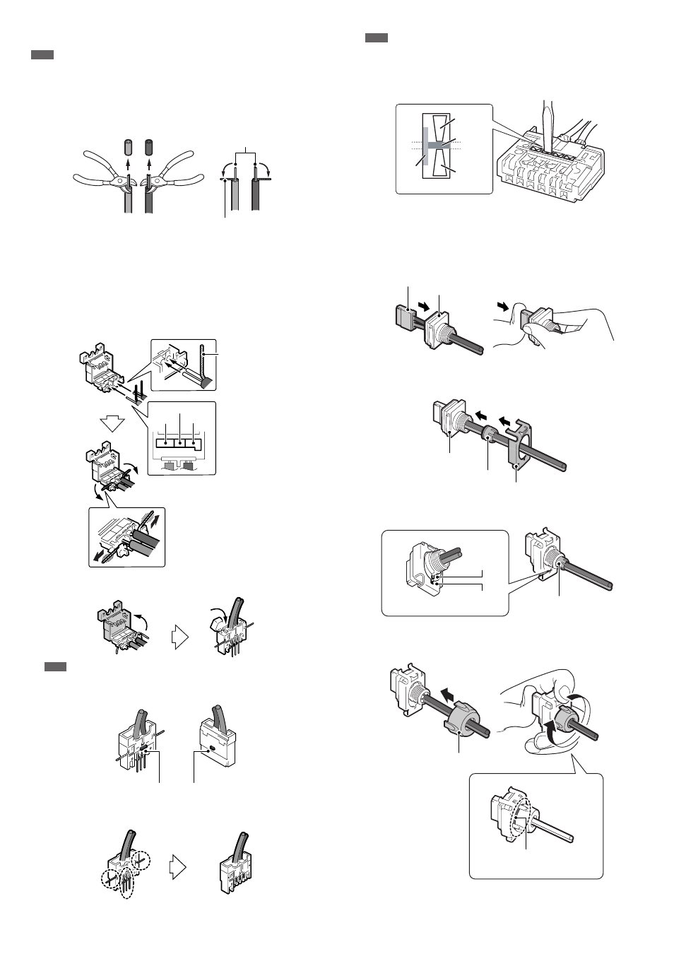
Connecting the Cables and the IDC Connector
Note
When the cable length of the sensor head is changed, be sure to connect the amplifier
to check that it operates correctly.
1
Manipulate the end of the cables as shown in the following figure.
• Peel back the insulation 10 mm from the end. (Do not strip the wires in the core.)
• Twist the base of the shielded wire at least five times so it does not unravel,
and bend it 90° to the side.
* Be careful not to twist the core wires along with the shielded wire.
If the wires become twisted, untwist them slightly and pull the core wires apart
from the shielded wires.
2
Align the core wires with the same color as indicated by the sticker on the IDC
connector and insert the wires as shown below.
• Insert the two wires (one black and one white) for the black cable (receiver
side) into the connector completely.
• The red wire for the gray cable (transmitter side) cannot be inserted
completely, but insert it as far as it can go.
• Twist the shielded wires in the direction of the arrow while pulling them into
the ditches.
3
Close the IDC connector, crimp it tight with pliers or a similar tool, and push
down on the top to lock it shut.
Note
Be careful not to crush the raised portion shown in the diagram when using pliers.
4
Use wire cutters or a similar tool to trim off the wires sticking out of the IDC
connector.
Note
Do not install the connectors more than two times. If the installation exceeds twice,
purchase OP-77758 (two connectors) separately.
If "ErH" appears on the amplifier even when using pliers to crimp the connector,
press the cable (part A) between the metallic contacts with a thin tool such as a
flathead screwdriver to crimp the cable more firmly.
Mounting the Connector
1
Install the IDC connector tight with Cap B.
2
Slide the packing and the mounting fixture in the direction of the arrow to
combine them.
Insert the packing into the hole in Cap B and combine the parts so that the
raised portion on Cap B lines up with the notch on the mounting fixture.
3
Push Cap A in the direction of the arrow and turn it clockwise to lock it into
place. Tighten Cap A while pushing on the IDC connector as shown in the
diagram below.
1
2
90
°
Core wires
90
°
Shielded wire
*
Red
White
Black
Shielded wire
Raised portion
Raised portion
Back
Front
Part A
Metallic
contact
Cable
Metallic
contact
IDC connector
Cap B
Mounting fixture
Cap B
Packing
Packing
Raised
portion
Cutout
Tighten the parts until there
is no gap between them.
Cap A