Shortening the sensor head cable – KEYENCE PX-10 User Manual
Page 8
8
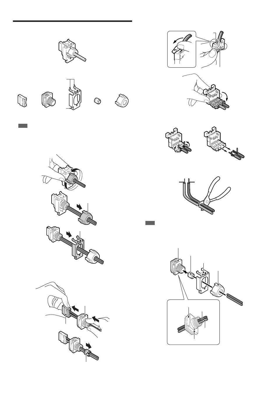
Shortening the Sensor Head Cable
Be sure to follow the steps carefully in order to waterproof the cable.
■
Sensor head connector
Disassembled diagram (configuration diagram)
The connector for the sensor head can be disassembled into the following parts.
* 1 Made up of two parts
Note
Do not remove parts other than the IDC connector from the cables.
Removing the Connector and Cutting the Cables
1
Turn Cap A counterclockwise and remove both Cap A and the mounting fixture.
2
Pull the IDC connector gently in the direction of the arrow to remove it from
Cap B. Remove the packing from Cap B.
3
Hold the IDC connector so that the back side (side where the wires can be
seen) is facing forwards. Push the upper tab in the direction of arrow 1 and
then open the back side in the direction of arrow 2.
4
Remove the cables.
5
Cut the cable to the required length.
Note
If all of the parts are accidentally removed, insert the cable through all of the parts as
shown below before starting the procedure under "Connecting the Cables and the IDC
Connector" (page 9).
•
Thread the gray cable through the hole near the raised portion of C a p B.
IDC connector
Cap B
Packing*
1
Cap A
Lower
tab
Upper tab
Mounting fixture
Mounting fixture
Cap A
IDC connector
Packing
Cap B
1
2
Back
(Wires are visible)
Upper tab
Cap B
Mounting fixture
Packing
Cap A
Cap B
Raised portion
Black (Receiver side)
Gray
(Transmitter side)