Brookfield YR-1 Rheometer User Manual
Page 15
Brookfield Engineering Labs., Inc.
Page 15
Manual No. M02-215-B0412
these fields until the check mark appears enables these parameters. Clicking the check box to
the left of these fields until the check mark disappears disables these parameters.
Clicking the New button (or selecting New from the File menu) sets all parameters to their
default values.
All open, save, and print operations selected while this page is displayed will open, save, and
print test parameters, but NOT data.
II.3.1
Program Number
This is the number of the memory slot in the YR-1 Rheometer to which the test parameters will
be loaded. There are ten (10) slots, numbered from 0 through 9.
II.3.2
Program Name
This descriptive user-supplied name is loaded into the memory slot in the YR-1 Rheometer with
the test parameters. A maximum of ten (10) alphanumeric characters may be used for this name.
II.3.3 Spindle
Spindle Number
A two (2) digit code representing the spindle number used for the test must be selected. See
Appendix A for more information regarding spindles for use with the YR-1 Rheometer. Selec-
tion of the appropriate spindle code is important to ensure correct stress calculations.
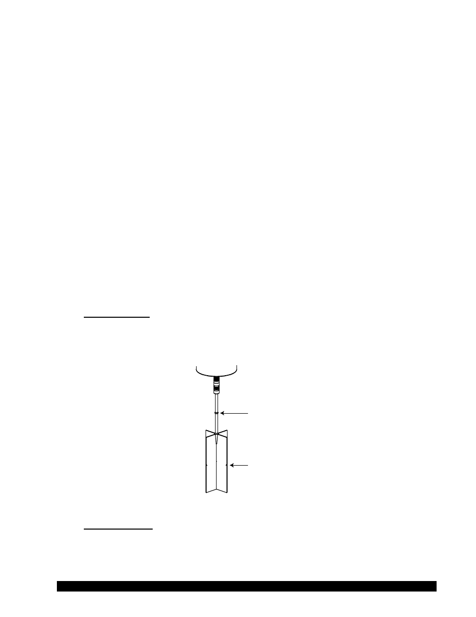
Primary
Immersion
Mark
Secondary
Immersion
Mark
Figure II-2
Immersion Mark
Each vane spindle has two (2) immersion marks. The primary immersion mark is located on the
spindle shaft. Normally, the spindle should be inserted so that the sample reaches this mark. If
the sample container is too small to allow the spindle to be inserted to this mark, the secondary