Aviom 6416o User Manual
Page 78
69
b
uildiNg
A
P
ro
64 N
etwork
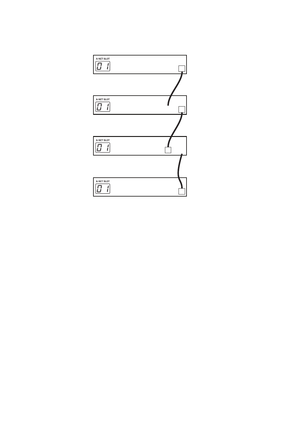
Example 6: Two input modules and two output modules, 16x16
B A
B A
Input
B A
Output
B A
Input
B A
Output
B A
Input
B A
Input
B A
Output
1 2
Merger
3 4 5 6 7 8 9 10
B A
B A
Input
B A
Output
B A
Input
B A
Output
B A
Input
B A
Input
B A
Output
1 2
Merger
3 4 5 6 7 8 9 10
B A
B A
Input
B A
Output
B A
Input
B A
Output
B A
Input
B A
Input
B A
Output
1 2
Merger
3 4 5 6 7 8 9 10
B A
B A
Input
B A
Output
B A
Input
B A
Output
B A
Input
B A
Input
B A
Output
1 2
Merger
3 4 5 6 7 8 9 10
Audio from the Pro64 input module at the bottom of the diagram is heard at
the output module shown at the top of the diagram.
In this example, two input modules are set to the same A‑Net Slot range (01).
Both modules are set to send their A‑Net data out of Port A. Unique data
flows in each direction in a 16x16 configuration. Each output module will
receive data from only one of the input modules in the configuration.
The next example refines this drawing by adding specific locations for the
modules in a traditional stage‑to‑FOH snake system.