Virtual data cable ports, Gpio, Gpio configuration dip switches – Aviom 6416o User Manual
Page 67: Virtual data cable ports gpio
58
r
eAr
P
ANel
F
eAtures
13 12 11 10 9 8 7 6 5 4 3 2 1
25 24 23 22 21 20 19 18 17 16 15 14
The pins on the panel-mounted DB25 jacks are
numbered according to the diagram above.
The DB25 panel‑mount connectors have #4‑40 UNC thread.
N
ote
: Strain relief is suggested when using DB25 cable assemblies. DB25
breakout cables should always be supported when connected to a
Pro64 product to reduce the risk of damaging the Pro64 product’s
rear panel.
Virtual Data Cable Ports
Three types of Virtual Data Cable (VDC) ports are available on the rear panel
of the 6416o Output Module. See the VDC info (page 33) for help configuring
and using the fourteen available Virtual Data Cables.
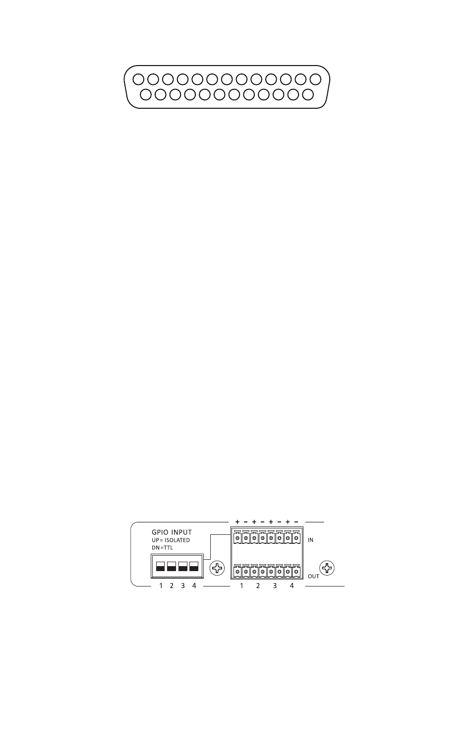
GPIO
GPIO (General Purpose Input/Output) can be used to send contact closure
or voltage‑type control signals through the network. Four input and four
output blocks are provided. Each terminal block can be individually wired.
GPIO inputs can be individually configured to be either Isolated or TTL.
GPIO Configuration DIP Switches
Each of the four GPIO Input blocks can be set to either Isolated or TTL
operation using the configuration switches to the left of the terminal blocks.
The Isolated/TTL configuration switches only apply to the GPIO inputs.
With the switch in the down position, the input is set to TTL. Use this setting
for voltage‑type signals. GPIO inputs set for TTL operation can handle signal
voltages up to 5 Volts.