360 Systems TCR Multi-Track User Manual
Page 32
2-16 Overview
TCR Series User's Manual
Video Reference Input
The VIDEO REF IN connector (BNC) accepts an analog video signal such as Black Burst,
for synchronizing the TCR to a common “house” reference.
LTC Input
The LTC IN connector accepts a standard longitudinal time code input signal.
LTC Output
The LTC OUT connector provides a standard longitudinal time code output signal, that
matches the current time code display.
Note
In Appendix C, refer to the “Connector Pinouts” section for details
and diagrams of all sync and reference connections.
Termination Switches
A four-position DIP switch is provided for termination.
•
UP = unterminated
•
DOWN = terminated
Termination DIP Switch Positions
Switch
Name
Description
S1
WCLK TERM
Selects a 75 ohm termination for the Word Clock input
S2
VITC TERM
Selects a 75 ohm termination for the VITC input
S3
VIDEO TERM
Selects a 75 ohm termination for the Video Reference input
S4
S4
Unused
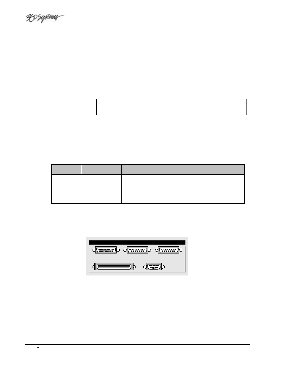
Control Section
The Control Section provides a group of connectors used for remote control, ganging multiple
machines, and connecting external drives.
P2
CONTROL IN
CONTROL OUT
GPI/O
SCSI
CONTROL
Control Input
The CONTROL IN/OUT connectors are a proprietary bus used to control and synchronize
multiple TCR units. For example, two TCR8 recorders might be interconnected to produce
16-channel capability.
The CONTROL IN port is connected to the previous CONTROL OUT port in line.