Control input and output connector pinouts, P2 connector pinouts, Connector type: 15-pin d – 360 Systems TCR Multi-Track User Manual
Page 146: Pin # signal pin # signal, Connector type: 9-pin d female
TCR Series User's Manual
Appendix C. Specifications 9-5
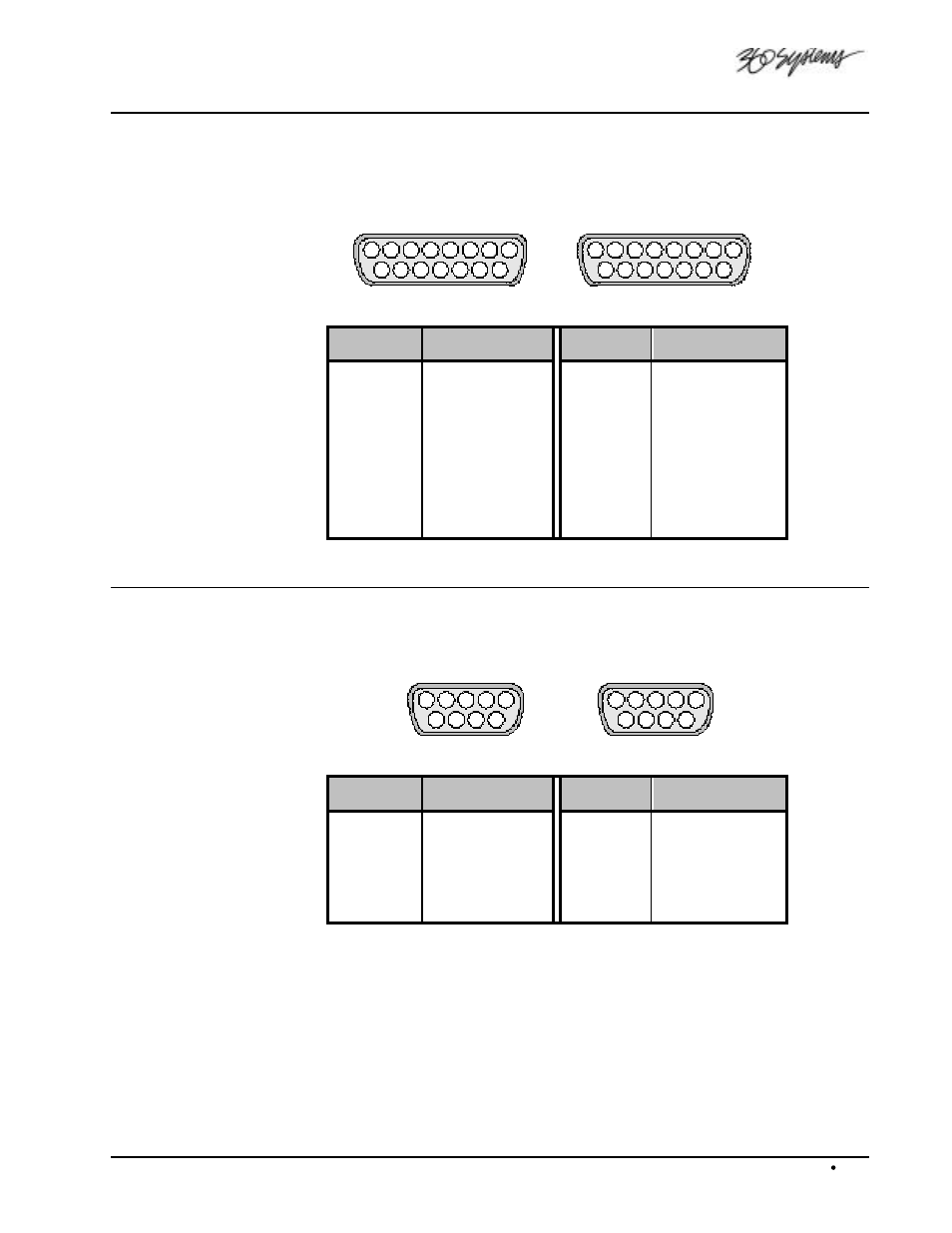
Control Input and Output Connector Pinouts
Cables for the input and output ports are identical.
Connector type: 15-pin D
5
4
3
2
1
9
10
11
12
6
7
8
13
14
15
Female on Chassis
5
4
3
2
1
9
10
11
12
6
7
8
13
14
15
Male on Cable
Pin #
Signal
Pin #
Signal
1
TX0
9
RX0
2
TX1
10
RX1
3
TX2
11
RX2
4
VD
12
GND
5
—
13
—
6
—
14
GND
7
GND
15
+ 12V
8
+ 12V
P2 Connector Pinouts
Connector type: 9-pin D Female
5
4
3
2
1
9
6
7
8
Female on Chassis
1
2
3
4
5
6
9
8
7
Male on Cable
Pin #
Signal
Pin #
Signal
1
Chassis
6
Chassis
2
RxA (Rx-)
7
RxB (Rx+)
3
TxB (Tx+)
8
TxA (Tx-)
4
n/c
9
n/c
5
Ground