Compaq 9900 User Manual
Page 116
102 Chapter
5
Planning for Installation and Operation
c *1
9.8"
*3
*2
4.6"
4.6"
2.4"
8.8"
b *1
a *1
G
Caster
Screw jack
26.8"
2.4"
2.4"
4.5"
4.5"
22.4"
(Unit: inches)
31.5"
7.9"
20.9"
94.5"
Floor cutout area for cables
Service clearance
2.75"
11.8"
9.8"
*3
26.8"
2.4"
22.2"
15.75"
*3
3.5"
18.1"
3.4"
22.75"
3.4"
11.8"
6.5"
16.5"
6.5"
53.1"
23.6"
28.3"
0.6"
0.6"
Front
5.9"
9.5"
31.5"
31.5"
DKC410I
DKU405I
G
G
Grid panel
(over 17.7" x 17.7")
d
G
G
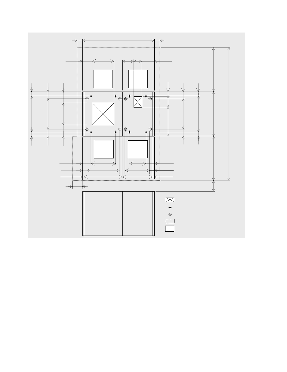
*1: Clearance (a+b) depends on the floor load rating and clearance c (see section 5.5.3).
*2: Clearance (d) is required over 0.28 m (11”) so as to open the DKC front door (refer to Figure 5.14). In case that clearance (d) is less than
clearance (a), give priority to clearance (a).
*3: Refer to Figure 5.14 for details on the DKC floor cutout.
Figure 5.19 9960 Disk Subsystem Minimum Configuration (inches)
- Netelligent 8500 (3 pages)
- 127453-B21 (4 pages)
- AlphaPC 164LX (82 pages)
- QUICKSPECS 294162-B21 (1 page)
- PowerLeap JP2 (6 pages)
- 5900 (1 page)
- 517212-001 (26 pages)
- SmartCore Express SMA200 (42 pages)
- 212953-B21 (2 pages)
- NC3132 (4 pages)
- 705 (2 pages)
- au-Series (11 pages)
- AlphaPC 164SX (72 pages)
- 21264 (356 pages)
- PROLIANT 3000 (137 pages)
- ProLiant p-Class (24 pages)
- TL895 (10 pages)
- Microcom 420 (2 pages)
- uSign Signature Capture Module uSign 200 (18 pages)
- Universal Notebook Power Adapter SPS-2406 (4 pages)
- RAID ARRAY 3000 EK-SMCPO-UG. C01 (112 pages)
- DA-10121 (3 pages)
- AlphaStation XP1000 (16 pages)
- MICROSPACE MSEBX800 (53 pages)
- Contec RS-232C (77 pages)
- SDLT 220GB (8 pages)
- Cabinet H9A11 (32 pages)
- MTEK6000 (81 pages)
- SANetworks Network View DA10682 (6 pages)
- AA-RHGWB-TE (320 pages)
- OXYGEN VX1 (29 pages)
- COM Express Extension (24 pages)
- Lithium-ion battery (7 pages)
- 164SX (72 pages)
- 3200 (211 pages)
- AA-Q88CE-TE (320 pages)
- MSB900L (66 pages)
- WL100 (2 pages)
- Wireless LAN 100 (2 pages)
- 1000 LX (4 pages)
- AAR-88LB-TE (42 pages)
- PC100 (66 pages)
- VAX 7000 Model 810 (9 pages)
- 99875320-5 (44 pages)
- CP-2E (91 pages)