Compaq 9900 User Manual
Page 112
98 Chapter
5
Planning for Installation and Operation
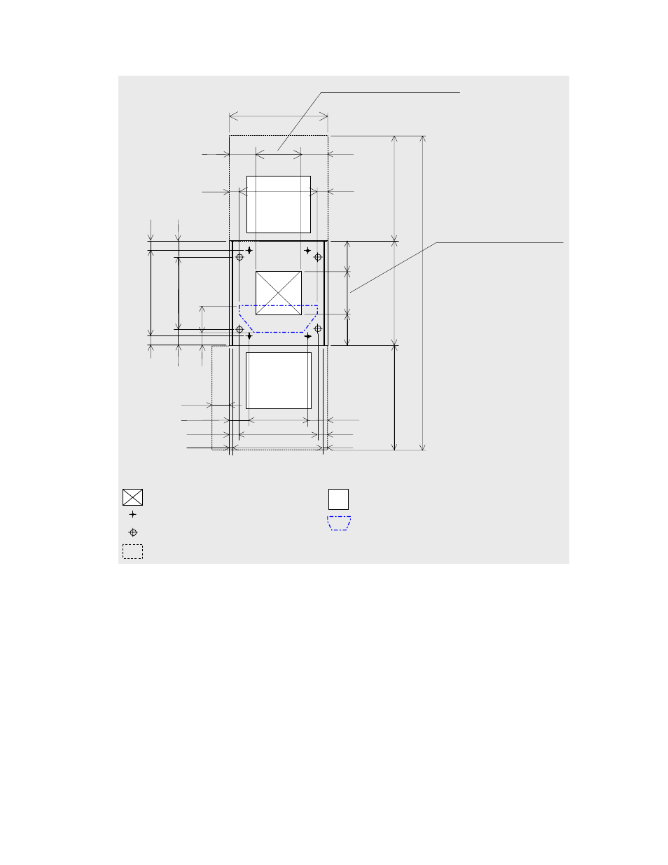
Floor cutout area for cables
Caster
Screw jack
Service clearance
G
Grid panel (over 17.7"
× 17.7")
Opening on the bottom of the frame
(for external cable entry)
(Unit : inches)
31.5"
9.8"
*2
9.8"
*2
94.5"
26.8"
2.4"
2.4"
4.6"
4.6"
22.2"
Front
6.9"
*2
6.9"
*2
3.4"
3.4"
22.75"
0.6"
0.6"
28.3"
6.5"
6.5"
16.5"
29.5"
31.5"
31.5"
G
G
11"
23.5"
3"
3"
3.9"
10"
Recommended value: 15.75"
( 11.8" - 22.4" ) *1
Recommended value: 11.8"
( 9.8" - 15.75" ) *1
*1: Values in parentheses show allowable range of the floor cutout dimension. The floor cutout should be planned in the center
of the DKC. In case that the floor cutout is planned in a right position for the external cable work and it is within the allowable
range, the cutout position may be off-center. In this case, check the relation between the positions of the cutout and the opening
on the bottom of the frame. If the floor cutout width is planned more than 520 mm, be careful about the restriction of the movable
direction because there is a possibility that the caster wheels fall down into the cutout.
*2: These dimensions vary with the floor cutout dimension.
Figure 5.15 9960 Controller Frame Service Clearance and Cutouts (inches)