Compaq 9900 User Manual
Page 115
Hitachi Lightning 9900™ User and Reference Guide
101
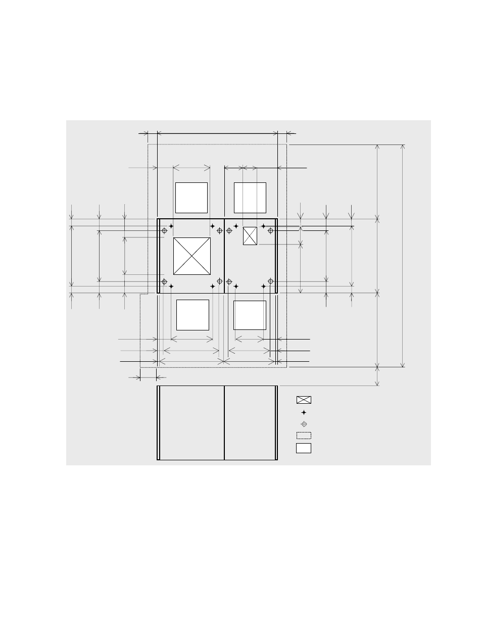
5.5.2 Minimum Subsystem Disk Configuration
Figure 5.18 and Figure 5.19 illustrate the 9960 and 9910 subsystem minimum configuration.
Figure 5.20 and Figure 5.21 illustrate all configurations of the 9960 and 9910 subsystems.
c
*1
250
*3
*2
118
118
60
225
b
*1
a
*1
G
Caster
Screw jack
680
60
60
115
115
570
(Unit: mm)
800
200
530
2400
Floor cutout area for cables
Service clearance
70
300
250
*3
680
60
564
400
*3
90
460
86
578
86
300
166
418
166
1350
600
718
16
16
Front
150
241
800
800
DKC410I
DKU405I
G
G
Grid panel
(over 450mm x 450mm)
d
G
G
*1: Clearance (a+b) depends on the floor load rating and clearance c (see section 5.5.3).
*2: Clearance (d) is required over 0.28 m so as to open the DKC front door (refer to Figure 5.14). In case that clearance (d) is less than
clearance (a), give priority to clearance (a).
*3: Refer to Figure 5.14 for details on the DKC floor cutout.
Figure 5.18 9960 Disk Subsystem Minimum Configuration (millimeters)
- Netelligent 8500 (3 pages)
- 127453-B21 (4 pages)
- AlphaPC 164LX (82 pages)
- QUICKSPECS 294162-B21 (1 page)
- PowerLeap JP2 (6 pages)
- 5900 (1 page)
- 517212-001 (26 pages)
- SmartCore Express SMA200 (42 pages)
- 212953-B21 (2 pages)
- NC3132 (4 pages)
- 705 (2 pages)
- au-Series (11 pages)
- AlphaPC 164SX (72 pages)
- 21264 (356 pages)
- PROLIANT 3000 (137 pages)
- ProLiant p-Class (24 pages)
- TL895 (10 pages)
- Microcom 420 (2 pages)
- uSign Signature Capture Module uSign 200 (18 pages)
- Universal Notebook Power Adapter SPS-2406 (4 pages)
- RAID ARRAY 3000 EK-SMCPO-UG. C01 (112 pages)
- DA-10121 (3 pages)
- AlphaStation XP1000 (16 pages)
- MICROSPACE MSEBX800 (53 pages)
- Contec RS-232C (77 pages)
- SDLT 220GB (8 pages)
- Cabinet H9A11 (32 pages)
- MTEK6000 (81 pages)
- SANetworks Network View DA10682 (6 pages)
- AA-RHGWB-TE (320 pages)
- OXYGEN VX1 (29 pages)
- COM Express Extension (24 pages)
- Lithium-ion battery (7 pages)
- 164SX (72 pages)
- 3200 (211 pages)
- AA-Q88CE-TE (320 pages)
- MSB900L (66 pages)
- WL100 (2 pages)
- Wireless LAN 100 (2 pages)
- 1000 LX (4 pages)
- AAR-88LB-TE (42 pages)
- PC100 (66 pages)
- VAX 7000 Model 810 (9 pages)
- 99875320-5 (44 pages)
- CP-2E (91 pages)