Parameter settings, H y s 1, H y s 2 – Beckett RWF40 Manual User Manual
Page 37: H y s 3
HVAC Products
CC1B7865en
01.09.2005
37/57
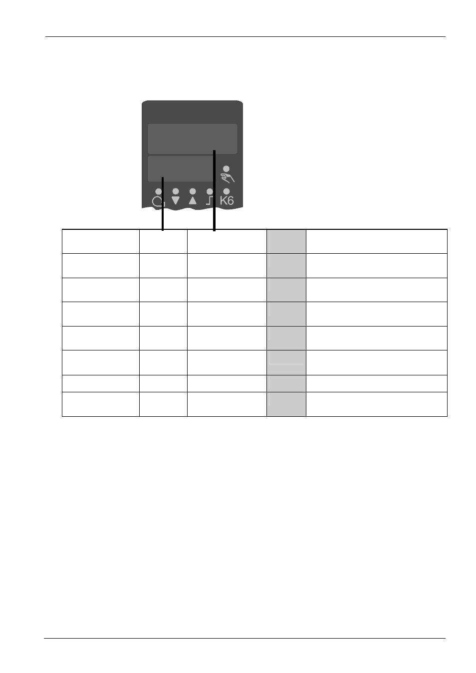
7. Parameter settings
The parameter is shown on the lower / setpoint display (green) and the parameter value
on the upper / actual value display (red).
Parameter
Display
Value range
Factory
setting
Remarks
Actuator running
time
tt
10...3000 s
15 s
Running time of the valve for use with
floating controllers
Switch-on threshold
for burner stage II
1)
H Y S 1
0...-199.9 digit
-5
Ö
Section 5.5.1 «Heating curve slope»
Switch-off threshold
stage II
1)
H Y S 2
0...HYS3 digit
3
Ö
Section 5.2 «High-fire operation»
Upper switch-off
threshold
1)
H Y S 3
0...999.9 digit
5
Ö
Section 5.2 «High-fire operation»
Response threshold
q
0...999.9
0
Ö
Section 5.6 «Response threshold
Q»
Heating curve slope
H
0...4
1
Ö
Section 5.5.1 «Heating curve slope»
Parallel
displacement
1)
P
-90...+90
0
Ö
Section 5.5 «Weather-dependent
setpoint shift»
1)
Setting of the decimal place has an impact on this parameter.
)
Note
When using the controller as a pure floating controller or modulating controller without
the burner release function (Q13, Q14), parameter «HYS1» must be set to
0 and
parameters «HYS2» and «HYS3» must be set to their
maximum values.
→ Otherwise, e.g. when using default parameter «HYS1» (factory setting -5), the
floating control loop will only be released when the control deviation reaches -5 K.
10
AL
7865p06/0200