Pilz PNOZ s22 C 24VDC 2 x 3 n/o 1 n/c User Manual
Page 2
- 2 -
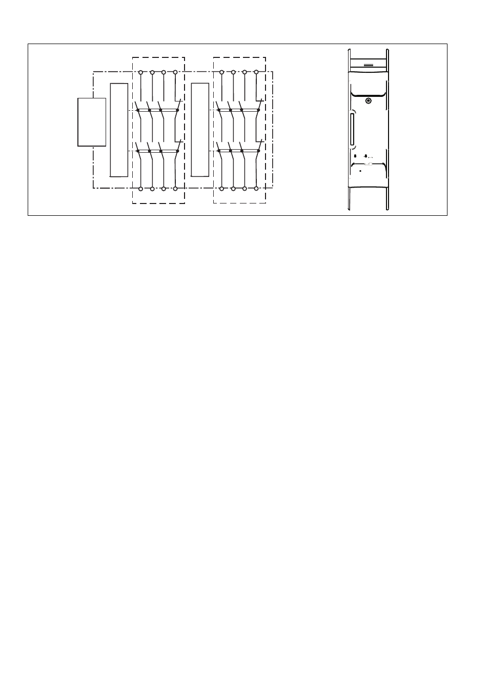
Blockschaltbild/Klemmenbelegung
Block diagram/terminal configuration Schéma de principe / affectation des
bornes
*Sichere Trennung nach EN 60947-1, 6 kV
*Safe separation in accordance with EN 60947-
1, 6 kV
* Séparation galvanique selon la norme EN
60947-1, 6 kV
Funktionsbeschreibung
1311796491
zweikanalige Ansteuerung und Spannungs-
versorgung über PNOZsigma Verbindungs-
stecker
je 3 Sicherheitskontakte und 1 Hilfskontakt
getrennt ansteuerbar
Function description
Dual-channel operation and supply voltage
via PNOZsigma connector
3 safety contacts and 1 auxiliary contact
each; these can be controlled separately
Description du fonctionnement
commande à deux canaux et tension d'ali-
mentation par le connecteur PNOZsigma
3 contacts de sécurité pour chaque et 1 con-
tact d'information pouvant être commandé
séparément
Montage
1311549195
Kontakterweiterungsblock mit PNOZ s30
oder Basisgerät PNOZmm0.1p/
PNOZ mm0.2p verbinden
Verbinden Sie den Kontakterweiterungs-
block mit dem mitgelieferten Verbindungs-
stecker.
Montage im Schaltschrank
Montieren Sie das Sicherheitsschaltgerät in
einen Schaltschrank mit einer Schutzart von
mindestens IP54.
Befestigen Sie das Gerät mit Hilfe des Rast-
elements auf der Rückseite auf einer Norm-
schiene.
Sichern Sie das Gerät auf einer senkrechten
Normschiene (35 mm) durch ein Halte-
element (z. B. Endhalter oder Endwinkel).
Vor dem Abheben von der Normschiene Gerät
nach oben oder unten schieben.
Installation
Connecting the contact expansion block to
the PNOZ s30 or base unit PNOZmm0.1p/
PNOZ mm0.2p
Connect the contact expansion block using
the connector supplied.
Control cabinet installation
The safety relay should be installed in a con-
trol cabinet with a protection type of at least
IP54.
Use the notch on the rear of the unit to attach
it to a DIN rail.
Ensure the unit is mounted securely on a ver-
tical DIN rail (35 mm) by using a fixing ele-
ment (e.g. retaining bracket or an end angle).
Push the unit upwards or downwards before
lifting it from the DIN rail.
Montage
Relier le bloc d'extension de contacts avec
le PNOZ s30 ou l'appareil de base
PNOZmm0.1p/PNOZ mm0.2p
Reliez le bloc d'extension de contacts avec
le connecteur fourni à la livraison.
Montage dans une armoire électrique
Montez le bloc logique de sécurité dans une
armoire électrique ayant un indice de protec-
tion d'au moins IP54.
Montez l'appareil sur un rail normalisé à
l'aide du système de fixation situé au dos de
l'appareil.
Sécurisez le montage de l'appareil monté sur
un rail normalisé vertical (35 mm) à l'aide
d'un élément de maintien (exemple : support
terminal ou équerre terminale).
Pour retirer l'appareil du rail normalisé, poussez
l'appareil vers le haut ou vers le bas.
Verdrahtung
1312353675
Beachten Sie:
Angaben im Abschnitt „Technische Daten“
unbedingt einhalten.
Verdrahtungshinweise in den Bedienungsan-
leitungen der Grundgeräte berücksichtigen.
Die Ausgänge 13 -14, 23 -24, 33 - 34 sind Si-
cherheitskontakte, die Ausgänge 41 - 42 sind
Hilfskontakte (z. B. für Anzeige).
Vor die Ausgangskontakte eine Sicherung
(s. techn. Daten) schalten, um das Ver-
schweißen der Kontakte zu verhindern.
Leitungsmaterial aus Kupferdraht mit einer
Temperaturbeständigkeit von 60/75 °C ver-
wenden.
Sorgen Sie an allen Ausgangskontakten bei
kapazitiven und induktiven Lasten für eine
ausreichende Schutzbeschaltung.
Wiring
Please note:
Information given in the “Technical details”
must be followed.
The wiring guidelines in the base units' oper-
ating instructions must be taken into ac-
count.
Outputs 13 -14, 23 -24, 33 - 34 are safety
contacts; outputs 41 - 42 are auxiliary con-
tacts (e.g. for display).
To prevent contact welding, a fuse should be
connected before the output contacts (see
technical details).
Use copper wire that can withstand 60/75
°C.
Sufficient fuse protection must be provided
on all output contacts with capacitive and in-
ductive loads.
Raccordement
Important :
Respecter impérativement les données indi-
quées dans la partie « Caractéristiques tech-
niques ».
Tenir compte des remarques relatives au câ-
blage présentes dans les manuels d'utilisa-
tion des appareils de base.
Les sorties 13 - 14, 23 - 24, 33 - 34 sont des
contacts de sécurité, les sorties 41 - 42 sont
des contacts d'information (par exemple
pour l'affichage).
Protection des contacts de sortie par des fu-
sibles (voir les caractéristiques techniques)
pour éviter leur soudage.
Utilisez uniquement des fils de câblage en
cuivre résistant à des températures de 60/
75 °C.
Assurez-vous du pouvoir de coupure des
contacts de sortie en cas de charges capaci-
tives ou inductives.
K3
K4
13 23
41
14 24
42
33
34
Interface PNOZ s30
PNOZ mm0.1p PNOZ mmo.2p
*
K1
K2
13 23
41
14 24
42
33
34
*
Ext.1
O0
Ext.2
O1
14 24 34 42
13 23 33 41
X3
X1
Ext.1/O0
PNOZ s22
14 24 34 42
13 23 33 41
X2
X4
Ext.2/O1