Pulse input card, Table 3-1. pulse input card – Rice Lake BCi Belt Scale - Installation and Operation Manual Version 2.03 User Manual
Page 35
Installation and Operation Manual - Integrator Hardware Setup
29
Pulse Input Card
Use the following procedure to install pulse input cards in the BCi integrator:
1. Disconnect the integrator from power source.
WARNING
Disconnect power before removing integrator backplate.
2. Place integrator face-down on an antistatic work mat. Remove screws that hold the backplate to the
enclosure body.
CAUTION
Use a wrist strap to ground yourself and protect components from electrostatic discharge (ESD)
when working inside the integrator enclosure.
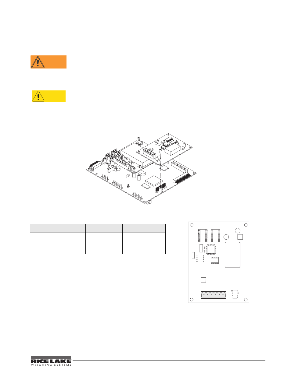
3. Carefully align the large option card connector with connector J6 on the
920i
CPU board. Press down to
seat the option card in the CPU board connector.
Use the screws and lockwashers provided in the option kit to secure the other end of the option card to the
threaded standoffs on the CPU board.
J6
Figure 3-3. Pulse Input Card
4. Make connections to the option card as required.
Table 3-2. Speed Wheel Pulse Input Wiring Colors
Speed Sensor Wire Color
Function
Pulse Input Card Pin
Brown
+12 V
1
Black
Pulse In
3
Blue
Ground
2
5. Use cable ties to secure loose cables inside the enclosure. Once cabling is complete, position the
backplate over the enclosure and reinstall the backplate screws. Use the torque pattern shown in the
backplate torque graphic on the next page to prevent distorting the backplate gasket. Torque screws to 15
in-lb (1.7 N-m).
6. Ensure no excess cable is left inside the enclosure and tighten cord grips.
+12V
J1
1
GND
PULSE IN
+12V
N/C
PULSE IN
2
2 3 4 5 6
N/C
N/C
The integrator automatically recognizes all installed
options cards when the unit is powered on. No hardware
specific configuration is required to identify the newly
installed card to the system.