3 belt travel speed wheel - optional, 4 magnetic shaft encoder - optional, Belt travel speed wheel - optional – Rice Lake BCi Belt Scale - Installation and Operation Manual Version 2.03 User Manual
Page 12: Magnetic shaft encoder - optional
6
Installation and Operation Manual
1.1.3
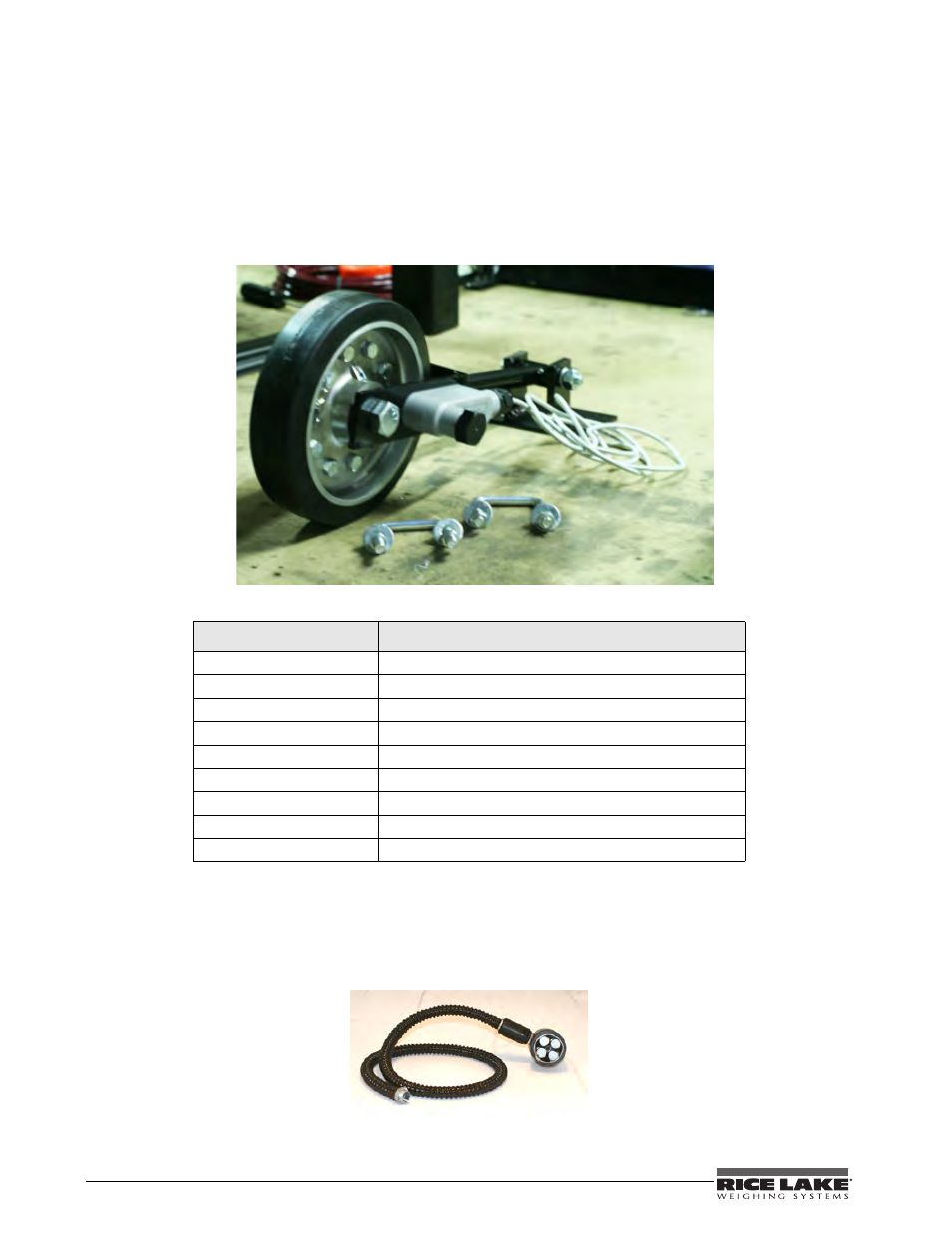
Belt Travel Speed Wheel - Optional
The belt travel speed wheel is located near the weigh frame. Positive contact must be maintained between the roll
and the belt for proper operation. The speed sensor should never come in contact with material that is being
conveyed along the belt. The signal generated by the speed wheel is converted by the integrator into a value that
represents belt travel distance. Various devices used for sensing belt travel include AC and DC generators,
mechanical belt or chain drives, photo-optical segmented disks, and electromagnetic pulse generators.
Installation procedures for the speed wheel are explained in detail on page 23. Figure 1-4 illustrates the major
component parts of the speed wheel.
Figure 1-4. Speed Wheel
Table 1-2. Speed Wheel Assembly Component Part Numbers
RLWS Part Number
Description (Quantity)
94969
Complete Speed Wheel Assembly (1)
96543
Speed Wheel (1) (wheel only)
94979
Speed Proximity Sensor (1)
94970
Speed Wheel Bracket Assembly (1) (wheel not included)
Cabling to integrator (1)
94980
U-Bolts (2)
21161
Splice Box (1)
98501
Expansion Cable - 20’
100038
Magnetic Shaft Encoder
1.1.4
Magnetic Shaft Encoder - Optional
Another option besides the belt travel speed wheel is a magnetic shaft encoder which can also be used to
determine belt travel distance like the speed wheel. The magnetic shaft encoder should never come in contact
with material that is being conveyed along the belt nor the belt itself. The signal generated by the encoder is
converted by the integrator into a value that represents belt travel distance.
Figure 1-5. Magnetic Shaft Encoder