0 integrator hardware setup, 1 enclosure disassembly, 2 cable connections – Rice Lake BCi Belt Scale - Installation and Operation Manual Version 2.03 User Manual
Page 33: Cable grounding, Integrator hardware setup, 1 enclosure disassembly 3.2 cable connections
Installation and Operation Manual - Integrator Hardware Setup
27
3.0
Integrator Hardware Setup
3.1
Enclosure Disassembly
The integrator enclosure must be opened to install option cards and to connect cables for installed option cards.
WARNING
The integrator has no on/off switch. Before opening the unit, ensure the power cord is disconnected
from the power outlet.
Ensure power to the integrator is disconnected, then place the integrator face-down on an antistatic work mat.
Remove the screws that hold the backplate to the enclosure body, then lift the backplate away from the enclosure
and set it aside.
3.2
Cable Connections
The universal model of the integrator provides six cord grips for cabling into the unit: one for the power cord,
five to accommodate cabling for option cards. Install plugs in all unused cord grips to prevent moisture from
entering the enclosure.
Cable Grounding
Except for the power cord, all cables routed through the cord grips should be grounded against the integrator
enclosure. Do the following to ground shielded cables:
•
Use the lockwashers, clamps, and keep nuts provided in the parts kit to install grounding clamps on the
enclosure studs adjacent to cord grips. Install grounding clamps only for cord grips that will be used; do
not tighten nuts.
•
Route cables through cord grips and grounding clamps to determine cable lengths required to reach cable
connectors. Mark cables to remove insulation and shield as described below:
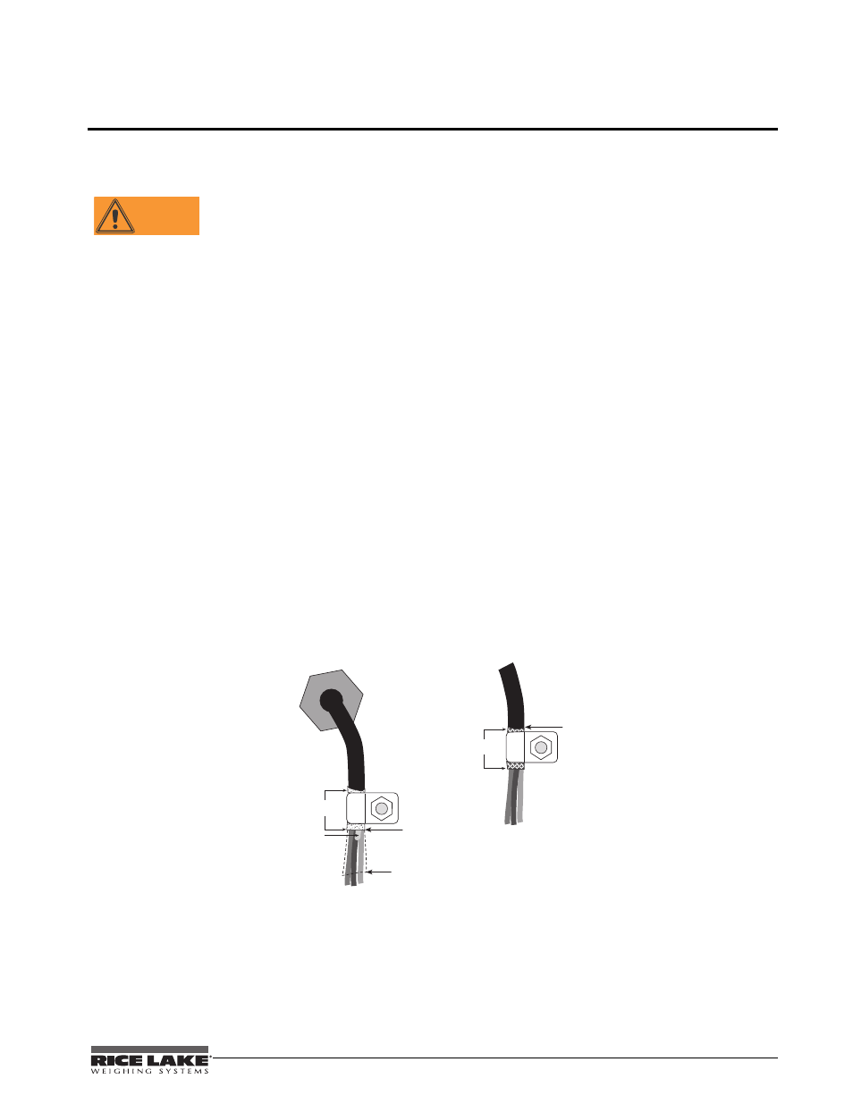
• For cables with foil shielding, strip insulation and foil from the cable half an inch (15 mm) past the
grounding clamp. Fold the foil shield back on the cable where the cable passes through the clamp.
Ensure silver (conductive) side of foil is turned outward for contact with the grounding clamp.
• For cables with braided shielding, strip cable insulation and braided shield from a point just past the
grounding clamp. Strip another half inch (15 mm) of insulation only to expose the braid where the cable
passes through the clamp (see Figure 3-1 below).
Cord grip
Insulated cable
Foil (silver side out)
Grounding clamp
Shield wire (cut)
Length of foil before folding
back on cable insulation
Cut insulation here
for foil-shielded cables
Braid
Cut insulation here
for braided cables
NOTE: Install lockwashers
first, against enclosure,
under grounding clamp
Figure 3-1. Grounding Clamp Attachment for Foil-Shielded and Braided Cabling
•
For load cell cables, cut the shield wire just past the grounding clamp. Shield wire function is provided
by contact between the cable shield and the grounding clamp.
•
Route stripped cables through cord grips and clamps. Ensure shields contact grounding clamps as shown
in the figure above. Tighten grounding clamp nuts.
•
Finish installation using cable ties to secure cables inside of integrator enclosure.