6 enclosure reassembly, 7 cpu board removal, 6 enclosure reassembly 2.7 cpu board removal – Rice Lake 920i Installation Manual V4.01 User Manual
Page 21
Installation
15
Expansion Board Serial Port Assignments
Serial port numbers are reserved for each option card
slot, regardless of the type of cards actually installed.
Two port numbers are reserved for each slot that could
contain a dual-channel serial expansion card.
Table 2-6 shows the port numbers assigned to each
slot.
For example, in a system with a two-card expansion
board, port assignments are reserved as shown in
Figure 2-12. If the only serial card installed in this
system is in SLOT 4 of the expansion board, the
system consists of serial ports 1–4 (on the CPU board)
and ports 11–12.
Figure 2-12. Serial Port Assignments, Two-Card Expansion
Board
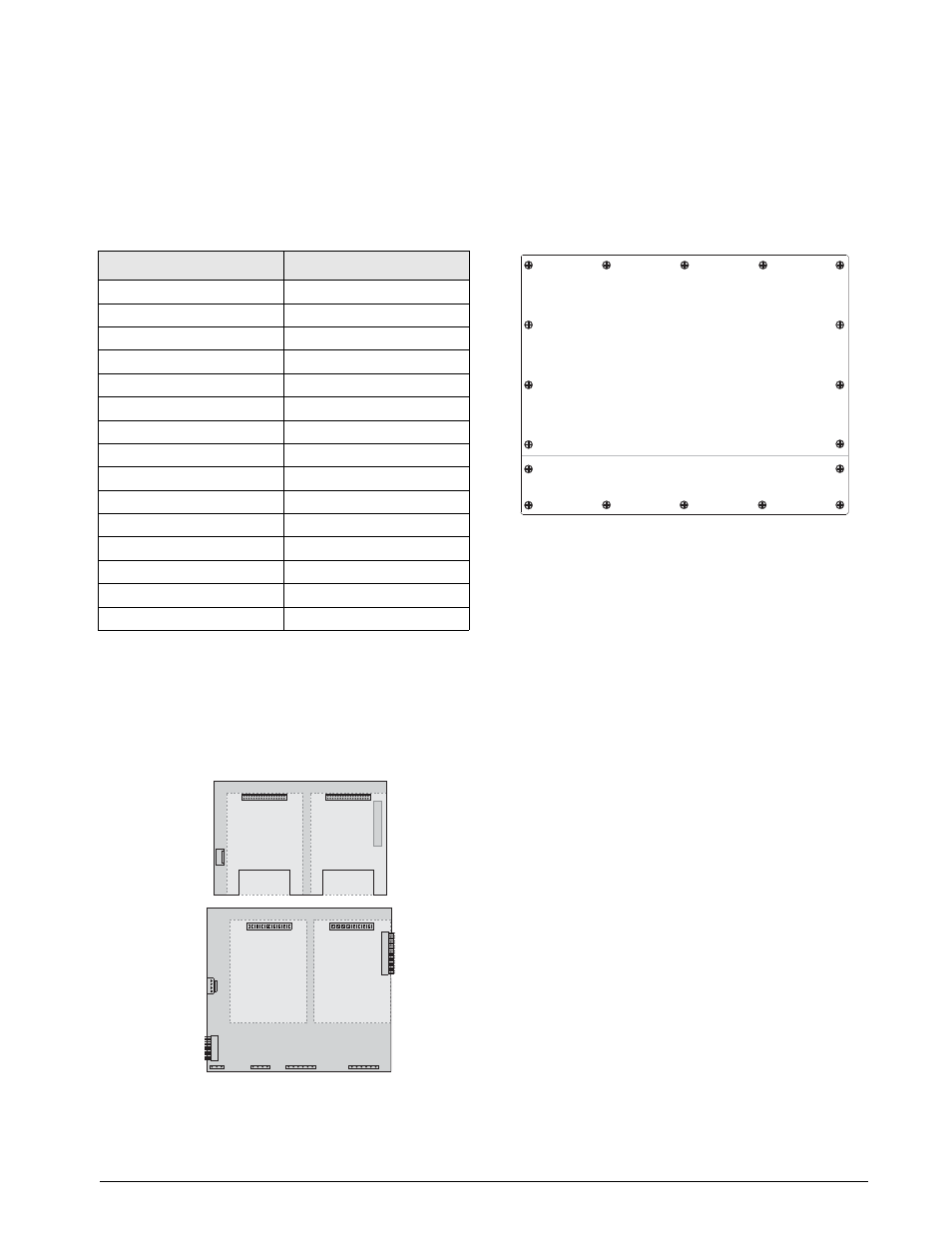
2.6
Enclosure Reassembly
Once cabling is complete, position the backplate over
the enclosure and reinstall the backplate screws. Use
the torque pattern shown in Figure 2-13 to prevent
distorting the backplate gasket. Torque screws to 15
in-lb (1.7 N-m).
Figure 2-13.
920i Enclosure Backplate
Torqued screws may become less tight as the gasket is
compressed during torque pattern, therefore a second
torque is required using the same pattern and torque
value.
2.7
CPU Board Removal
If you must remove the
920i
CPU board, use the
following procedure:
1. Disconnect power to the indicator. Remove
backplate as described in Section 2.2 on
page 8.
2. Unplug connectors J9, J10, and J11 (serial
communications), J2 (digital I/O), P1 (power
supply), and connectors to any installed
option cards.
3. Remove any installed option cards.
4. Remove the five phillips head screws and two
kep nuts from the CPU board.
5. Gently lift up the CPU board, then disconnect
connectors J12 (power to display), J4 (ribbon
cable, J3 (keypad connector), then the cable
J8 (Port 2 serial port).
6. Remove CPU board from the enclosure. If
necessary, cut cable ties to shift cables out of
the way.
To replace the CPU boa rd, reverse the above
procedure. Be sure to reinstall cable ties to secure all
cables inside the indicator enclosure.
Slot Number
Serial Port Assignments
CPU board
1–4
1
5–6
2
7–8
3
9–10
4
11–12
5
13–14
6
15–16
7
17–18
8
19–20
9
21–22
10
23–24
11
25–26
12
27–28
13
29–30
14
31–32
Table 2-6. Expansion Board Serial Port Assignments
SLOT 1
SLOT 2
CPU BOARD
1
SLOT 3
SLOT 4
SLOT 0
PORT
1
PORT
2
PORT
3
PORT
4
PORTS
5–6
PORTS
7–8
PORTS
9–10
PORTS
11–12
1
3
5
14
17
16
12
9
8
7
10
11
18
15
4
2
6
13
T o r q u e b a c k p l a t e s c r e w s
t o 1 5 i n - l b ( 1 . 7 N - m )