3 serial communications, Serial communications, The four communications ports on the – Rice Lake 920i Installation Manual V4.01 User Manual
Page 16
10
920i
Installation Manual
2.3.3
Serial Communications
The four communications ports on the
920i
CPU
board support full duplex RS-232, 20 mA output, or
RS-485 communications at up to 115200 bps.
To attach serial communications cables, route the
cable through the cord grip and ground the shield wire
as described in Section 2.3.1 on page 8. Remove the
serial connector from the CPU board and wire to the
connector. Once cables are attached, plug the
connector into the header on the board. Use cable ties
to secure serial cables to the inside of the enclosure.
Table 2-2 shows the pin assignments for Ports 1, 3,
and 4. Port 2 provides DIN-8 and DB-9 connectors for
remote keyboard attachment of PS/2-type personal
computer keyboards (see Figure 2-3; see Section 1.4
on page 4 for Contrast information). The DB-9
connector pin assignments for Port 2 are shown in
Ta b l e 2 - 3 ; s e e S e c t i o n 1 0 . 3 o n p a g e 11 0 f o r
information about the PS/2 keyboard interface.
Table 2-2. Serial Port Pin Assignments
Connector
Pin
Signal
Port
J11
1
GND
1
2
RS-232 RxD
3
RS-232 TxD
J9
1
GND / –20mA OUT
3
2
RS-232 RxD
3
RS-232 TxD
4
+20mA OUT
J10
1
GND / –20mA OUT
4
2
RS-232 RxD
3
RS-232 TxD
4
+20mA OUT
5
RS-485 A
6
RS-485 B
Serial ports are configured using the SERIAL menu.
See Section 3.2.2 on page 37 for configuration
information.
An optional dual-channel serial communications
expansion card, PN 67604, is also available. Each
serial expansion card provides two additional serial
ports, including one port that supports RS-485
communications. Both ports on the expansion card
can support RS-232 or 20mA connections.
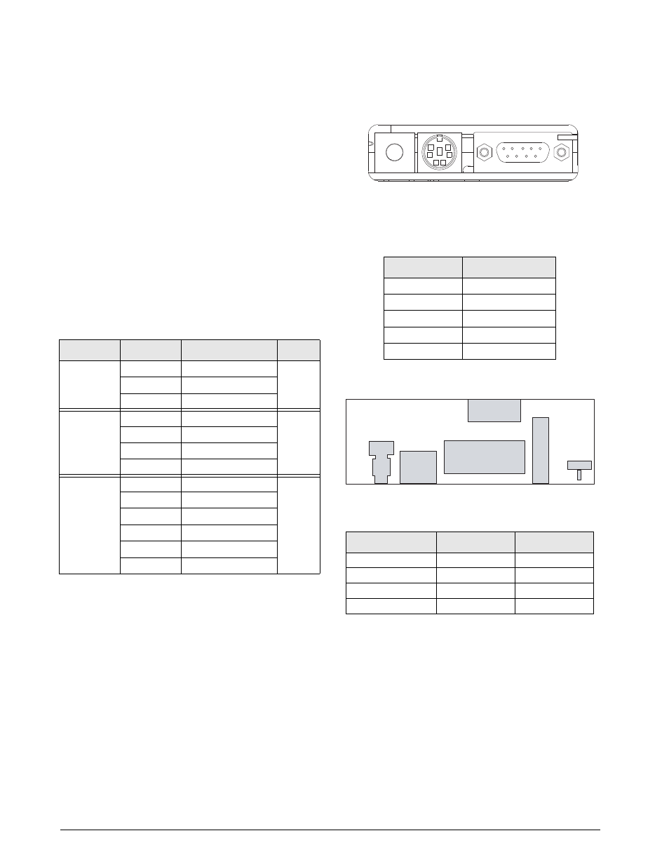
LCD Contrast
DIN-8 Connector for
PS/2 Remote Keyboard
DB-9 Connector
for Port 2 / J8
1
Figure 2-3. Interface Board Connections
Table 2-3. DB-9 Connector Pin Assignments
DB-9 Pin
Signal
2
TxD
3
RxD
5
GND
7
CTS
8
RTS
J1
J2
J3
J4
VR1
PB1
LCD
Contrast
DB-9 Connector
DIN-8
Connector
Setup
Switch
Optional
Keyboard Connector
1
CLK
PWR
RET
DA
T
Ribbon Cable Connector
to CPU Boar
d / J8
Figure 2-4. Interface Board, Top View
Table 2-4. J4 (Optional Keyboard Connector)
Pin Assignments
J4 Pin
Color
Signal
1
Brown
Clock
2
Clear
+5v
3
Yellow
GND
4
Red
Data