Bag h (continued) – Losi XXX-S Sport User Manual
Page 30
130
129
132
27
133
131
127
36
BAG H (Continued)
27
Step H-3
Step H-4
Figure 60
q
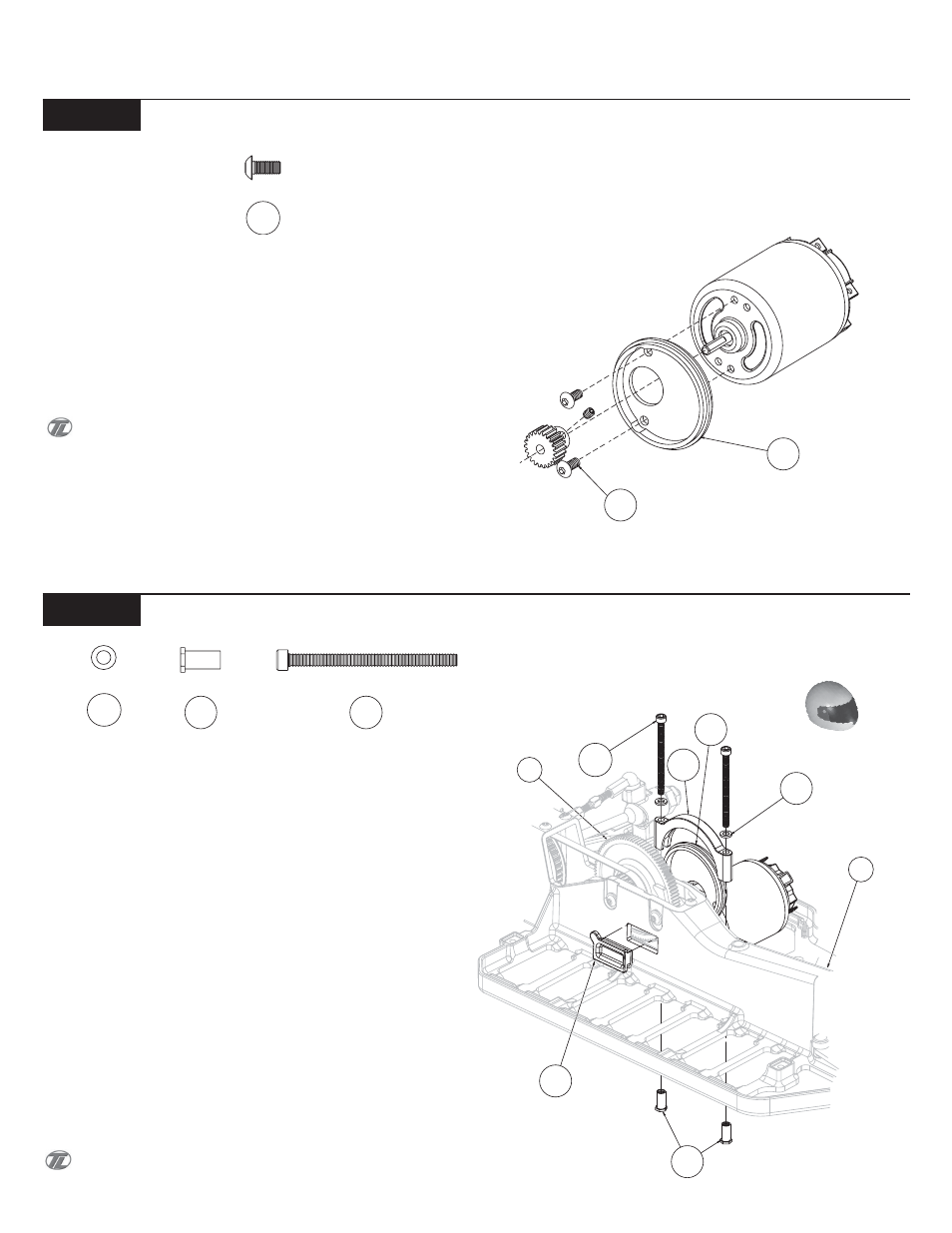
1. Place the Motor Mount (127) against the motor (not included)
so that the shaft on the motor is centered in the large hole in the
Motor Mount and the flat surface of the Motor Mount rests against
the motor as shown in Figure 58. Align the holes in the Motor Mount
with the holes in the motor as indicated in Figure 60.
q
2. Secure the motor plate to the motor by threading two 3mm x
6mm Button Head Screws (128) through the two holes in the Motor
Mount, and tightening..
If there are two sets of holes in the motor, thread the Screws
into the set of holes that will allow the power tabs to face the speed
control (ESC) with the motor in its lowest position in the Chassis.
This is the optimal location for your vehicle.
q
3. Attach the pinion gear (not included) to the motor shaft with
the tooth section of the gear away from the motor as shown.
q
1. Press two Threaded Inserts (131) into the bottom of the Chas-
sis (27) in the Holes with the Hex. Be sure that you line up the Hex on
the Insert with the Hex in the bottom of the Chassis. The Inserts
should be installed in the direction shown in Figure 61.
q
2. Install the Motor Mount (127), with the motor attached, in the
groove on the left side of the Chassis. Check alignment of the pinion
gear with the Spur Gear (36). If the two Gears don't align properly,
remove the motor and adjust the position of the pinion gear. Check
again for proper alignment.
q
3. Once the pinion gear is properly aligned with the Spur Gear,
place the Motor Strap (130) over the Motor Mount as shown. Slide a
Ball Stud Washer (129) over each of the 4-40 x 1.5" Cap Head Screws
(132). Thread a 4-40 x 1.5" Cap Head Screw through the two holes in
the Motor Mount Strap into the Threaded Inserts in the Chassis, but
don't tighten the Screws yet. Check the gear mesh by looking through
the opening in the right side of the Chassis. To adjust the gear mesh,
rotate the motor - clockwise to tighten the gear mesh; and counter-
clockwise to loosen the gear mesh. Once the gear mesh has been
adjusted, tighten the Motor Clamp Screws.
q
4. Insert the rectangular, Gear Mesh Access Plug (133), bevelled
side first, in the opening on the right side of the Chassis.
The gears need a small amount of backlash in order to function
properly.
131
132
129
127
128
Motor Plate Install
Motor Install
Figure 61
128