Bag d (continued) – Losi XXX-S Sport User Manual
Page 18
47
80
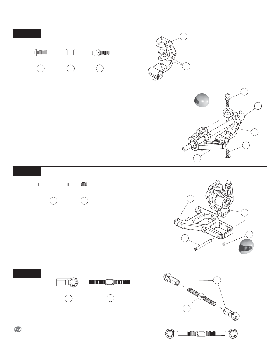
BAG D (Continued)
15
Step D-7
Figure 33B
Step D-8
Figure 34
Step D-9
Figure 35A
Figure 33A
Figure 35B
q
1. Insert two Carrier/Steering Bushings (47) into the upper and
lower holes in the Left 4 degree Spindle Carrier (80), (Marked with
"4 L") from the inside as shown in Figure 33A.
q
2. Attach the Left Spindle (70) to the Left Spindle Carrier by
sliding the CVD Dogbone (73) through the Spindle Carrier as illus-
trated in Figure 33B. Line up the holes in the Spindle and the Spindle
Carrier. Thread a Long, Short Head Ball Stud (68) through the Carrier
Bushing (47) into the Spindle from the top of the Spindle Carrier.
Thread a 4-40 x 5/16" Button Head Screw (24) through the Carrier
Bushing into the Spindle from the bottom of the Spindle Carrier.
q
3. Repeat Steps 1-2 for the Right Spindle (70) and Right 4 degree
Spindle Carrier (80), (Marked with "4 R") assembly.
24
47
81
q
1. Attach the Left Spindle and Carrier assembly to the Left Front
Arm (63) by aligning the holes in the Spindle Carrier (80) with the
holes in the Front Arm. Insert a 3/32" x .930" Hinge Pin (81) through
the Arm and the Spindle Carrier.
q
2. Make sure the Hinge Pin is centered between the ends of the
Arm. Secure the Hinge Pin by threading a 5-40 x 3/16" (82) Set Screw
into the bottom of the Spindle Carrier.
q
3. Repeat Steps 1-2 for the Right Arm (63) assembly.
q
1. Thread a Plastic Rod End (58) onto each end of a 1.250" Tita-
nium Turnbuckle (84). Tighten both Rod Ends equally until the Tierod
is the same length as the Tierod in Figure 35B. Make two of these Tie
rod assemblies.
Each end of the Turnbuckle is threaded opposite. One end
has right-hand threads, the other has left-hand threads. This allows
the length of the rods, once installed, to be adjusted without remov-
ing them.
58
Turnbuckle - Camber Link Assembly
Front Spindle Carrier Assembly
Front Arm Assembly
68
70
73
80
24
68
82
80
63
81
84
82
84
58