Kontron PCI-760 User Manual
Page 29
9. Jumpers and Connectors Overview
PCI-760 – User’s Guide (V1.10)
27
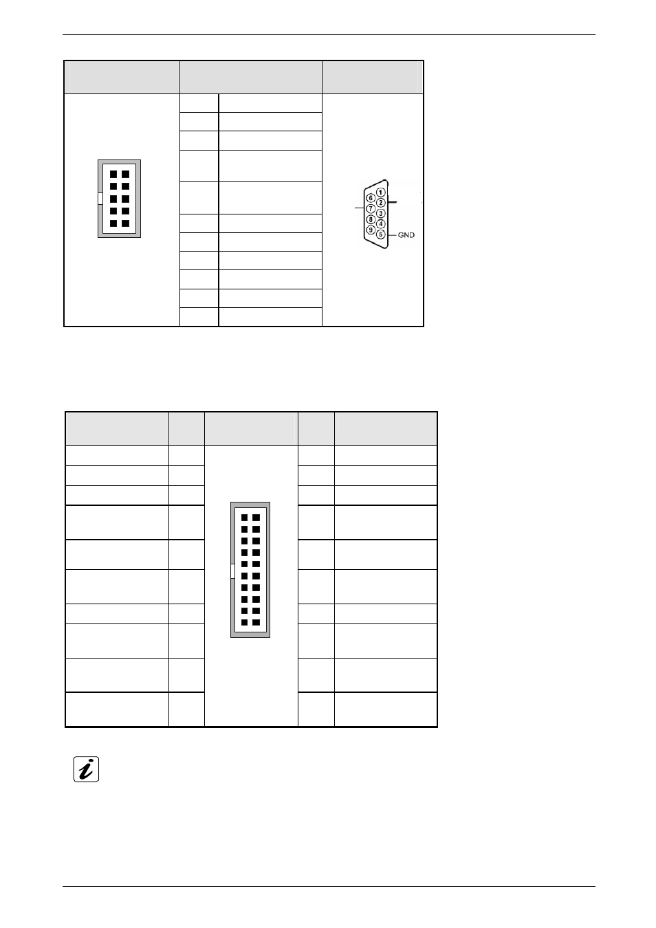
COM2 pin assignment as RS485:
J16: Boxed Header,
DIP 10-pin
RS485
(Pinning on the on-board header)
D-SUB
Connector
Pin #
Signal Name
1 NC
2 NC
3
TRxD–,
Transmit/Receive data
4
TRxD+,
Transmit/Receive data
5
12 V, fused
6 NC
7 NC
8 NC
9 GND,
ground
1
9
2
10
COM2
10
12 V, fused
Pining on the
supplied cable
connector:
TRxD–
TRxD+
9.1.3.11.
J7: Hardware Monitor & GPIO Connector
The hardware monitor & GPIO connector provides signals for hardware monitoring and allows you to monitor user
defined function GPIO[0-3].
Signal Name
Pin#
J7: Box Header,
DIP 20-pin
Pin#
Signal Name
GND 1
2
PWRBTN#
SMBALERT# 3
4
GND
EXT_SMBDATA 5
6
EXT_SMBCLK
APFLT# (GPIO[0])
(not supported)
7 8
CPUFLT# (GPIO[1])
(not supported)
* EXFLT# (GPIO[2])
(not supported)
9 10
GND
FANFLT# (GPIO[3])
(not supported)
11 12
GND
CHASINT# 13
14
GND
FAN_TACH1X(J4)
(not supported)
15 16
FAN_TACH2X(J24)
(not supported)
FAN_TACH3X
(not supported)
17 18
SIO_TACH4
(not supported)
SIO_TACH5
(not supported)
19
1
19
2
20
Hardware
Monitor & GPIO
20
SIO_TACH6
(not supported)
* EXFLT# (GPIO[2])
Use this pin for alarm signal of a redundant PSU.