Connectors on-board – Kontron PCI-760 User Manual
Page 24
9. Jumpers and Connectors Overview
22
PCI-760 – User’s Guide (V1.10)
9.1.3.
Connectors On-Board
9.1.3.1.
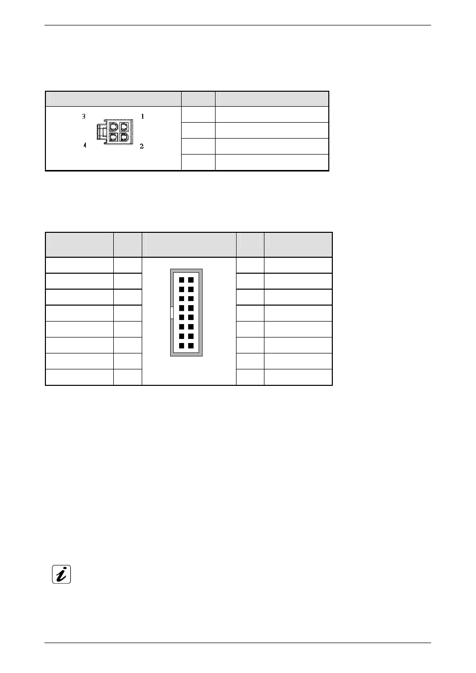
J31: +12V ATX Power Connector
The ATX connector is used to connect the +12V ATX power supply to the board in order to provide power to the CPU.
J31: 4-pin Connector
Pin
Signal Name
1 GND
2 GND
3 +12V
4 +12V
9.1.3.2.
J14: Multifunctional Connector
A system chassis can be equipped with components, that provide acoustical or/and light indication of the computer
activities, and switches to change the computer status. J14 is a 16-pin box header that provides following connections:
Signal Name
Pin #
J14: Boxed Header,
DIP 16-pin
Pin #
Signal Name
KBCKL 1
2
GND
KBDATA 3
4
GND
VCC5V fused
5
6
PWRLED+
Speaker 7
8
VCC5V
fused
MCKL 9
10
GND
MDATA 11
12
GND
PBRES# 13
14
GND
HDLED- 15
1
15
2
16
Multifunctional
16 HDLED+
The multifunctional connector (J5) provides an interface:
❏
for a PS/2 keyboard and a PS/2 mouse connector
❏
to a speaker for audio tone generation
❏
to connect the Power LED
❏
to connect the hard drive activity LED
❏
to connect the reset button
Power LED: pins 4 and 6
These-pins allow the connection of the power LED.
Reset Button: pins 13 and 14
To these pins can be connected a reset button. The reset button is used to restart the system without turning the main
power switch off and on again.
Depending on the software and operating system, some data may be lost if the reset button is activated.