14 pci express minicard, 1 connector, Jrex plus - dc user's guide – Kontron JRexplus-DC User Manual
Page 36
KTD-S0008-F
Page 31
PCI Express MiniCard
JRexplus-DC User's Guide
14 PCI Express MiniCard
PCI Express MiniCard (also known as Mini PCI Express, Mini PCIe and Mini PCI-E) is a replacement for the
Mini PCI form factor based on PCI Express. It is developed by the PCI-SIG. The host device supports both PCI
Express and USB 2.0 connectivity.
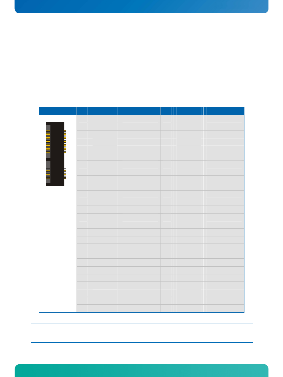
14.1 Connector
The interface is available through the standard PCI Express MiniCard connector J18 (52 pins).
Header
Pin Signal Name
Function
Pin Signal Name
Function
1
/WAKE
Wake event
2
VCC3
1)
Power +3.3V
3
N.C.
Not connected
4
GND
Ground
5
N.C.
Not connected
6
VCC1
1)
Power +1.5V
7
/CLKREQ
PCIe clock request
8
N.C.
Not connected
9
GND
Ground
10
N.C.
Not connected
11
REFCLK-
PCIe clock (neg.)
12
N.C.
Not connected
13
REFCLK+
PCIe clock (pos.)
14
N.C.
Not connected
15
GND
Ground
16
N.C.
Not connected
17
N.C.
Not connected
18
GND
Ground
19
N.C.
Not connected
20
/W_DISABLE
Wireless disable
21
GND
Ground
22
/PERST
PCIe reset
23
PERn0
PCIe receive (neg.)
24
VCC3AUX
1)
Power +3.3V aux
25
PERp0
PCIe receive (pos.)
26
GND
Ground
27
GND
Ground
28
VCC1
1)
Power +1.5V
29
GND
Ground
30
SMB_CLK
SMBus clock
31
PETn0
PCIe transmit (neg.)
32
SMB_DATA
SMBus data
33
PETp0
PCIe transmit (pos.)
34
GND
Ground
35
GND
Ground
36
USB-
USB port 0 (neg.)
37
GND
Ground
38
USB+
USB port 0 (pos.)
39
VCC3
1)
Power +3.3V
40
GND
Ground
41
VCC3
1)
Power +3.3V
42
/LED_WWAN
LED output
43
GND
Ground
44
/LED_WLAN
LED output
45
N.C.
Not connected
46
/LED_WPAN
LED output
47
N.C.
Not connected
48
VCC1
1)
Power +1.5V
49
N.C.
Not connected
50
GND
Ground
1
51
N.C.
Not connected
52
VCC3
1)
Power +3.3V
Note:
1)
To protect the external power lines of peripheral devices make sure that
- the wires have the right diameter to withstand the maximum available current.
- to enclosure of the peripheral device fulfills the fire-protecting conditions of IEC/EN 60950.