Kontron JRexplus-DC User Manual
Page 20
KTD-S0008-F Page
15
Graphics
Interface
JRexplus-DC User's Guide
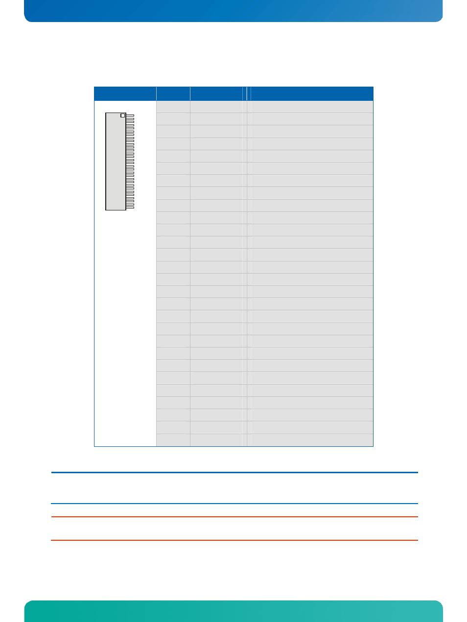
7.3.1 JILI30
Connector
Header
Pin
Signal Name
Function
1
FTX0-
First channel data output 0 (negative)
2
FTX0+
First channel data output 0 (positive)
3
FTX1-
First channel data output 1 (negative)
4
FTX1+
First channel data output 1 (positive)
5
FTX2-
First channel data output 2 (negative)
6
FTX2+
First channel data output 2 (positive)
7
GND
Ground
8
FTXC-
First channel clock output (negative)
9
FTXC+
First channel clock output (positive)
10
FTX3-
First channel data output 3 (negative)
11
FTX3+
First channel data output 3 (positive)
12
STX0-
Second channel data output 0 (negative)
13
STX0+
Second channel data output 0 (positive)
14
GND
Ground
15
STX1-
Second channel data output 1 (negative)
16
STX1+
Second channel data output 1 (positive)
17
GND
Ground
18
STX2-
Second channel data output 2 (negative)
19
STX2+
Second channel data output 2 (positive)
20
STXC-
Second channel clock output (negative)
21
STXC+
Second channel clock output (positive)
22
STX3-
Second channel data output 3 (negative)
23
STX3+
Second channel data output 3 (positive)
24
GND
Ground
25
SDA
I2C data line
26
DATAENA
Data enable output
27
SCL
I2C clock line
1
30
28 - 30
VCC
1)
Power +3.3V or +5V
Note:
1)
To protect the external power lines of peripheral devices make sure that
- the wires have the right diameter to withstand the maximum available current.
- to enclosure of the peripheral device fulfills the fire-protecting conditions of IEC/EN 60950.
Warning:
Check jumper J2 (panel power) for correct settings for your panel – not doing so might cause permanent damage
to your panel.