7 com1/com2 (j23/j22), Com1/com2 (j23/j22) – Kontron KTA70M-mITX User Manual
Page 37
KTD-N0861-B
Page 30
Pin Connectors
KTA70M/mITX Users Guide
KTA70M/mITX Users Guide
7.7
COM1/COM2 (J23/J22)
Two serial ports provide asynchronous serial communication via RS-232 interfaces. The connector is type
Pinrex 512-90-10GBE5 or similar.
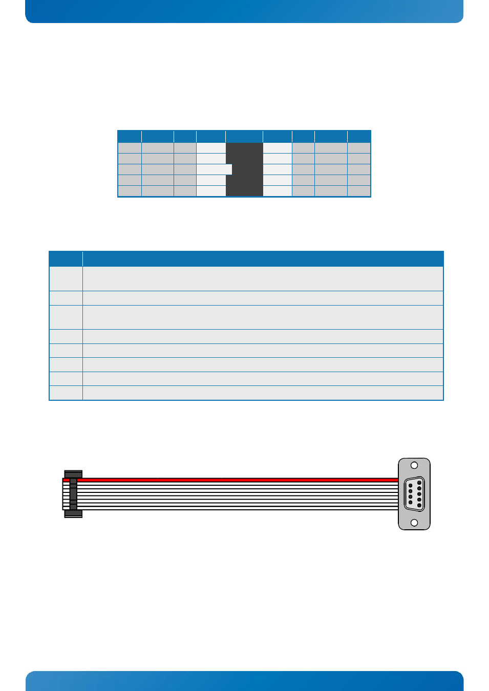
The pinout of Serial ports COM1 and COM2 is as follows:
Note Ioh/Iol Type Signal
PIN
Signal Type Ioh/Iol Note
-
I
DCD
1 2
DSR
I
-
-
I
RxD
3 4
RTS
O
O
TxD
5 6
CTS
I
-
O
DTR
7 8
RI
I
-
-
PWR GND
9 10
5V
PWR
-
1
Note 1: The COM1 and COM4 5V supply is fused with a common 1.1A resettable fuse.
The typical definition of the signals in the COM ports is as follows:
Signal Description
TxD
Transmitted Data, sends data to the communications link. The signal is set to the marking state (-
12V) on hardware reset when the transmitter is empty or when loop mode operation is initiated.
RxD
Received Data, receives data from the communications link.
DTR
Data Terminal Ready, indicates to the modem etc. that the on-board UART is ready to establish a
communication link.
DSR
Data Set Ready, indicates that the modem etc. is ready to establish a communications link.
RTS
Request To Send, indicates to the modem etc. that the on-board UART is ready to exchange data.
CTS
Clear To Send, indicates that the modem or data set is ready to exchange data.
DCD
Data Carrier Detect, indicates that the modem or data set has detected the data carrier.
RI
Ring Indicator, indicates that the modem has received a ringing signal from the telephone line.
Available cable kit (DB9 adapter cables):
PN 821017 - 100 mm or PN 821016 - 200 mm