5 jumper area (j34, j35, j36, j37), Jumper area (j34, j35, j36, j37) – Kontron KTA70M-mITX User Manual
Page 35
KTD-N0861-B
Page 28
Pin Connectors
KTA70M/mITX Users Guide
KTA70M/mITX Users Guide
Don’t leave the Clear CMOS jumper in position 1-2, otherwise if power is
disconnected, the battery will fully deplete within a few weeks.
Warning
!
7.5
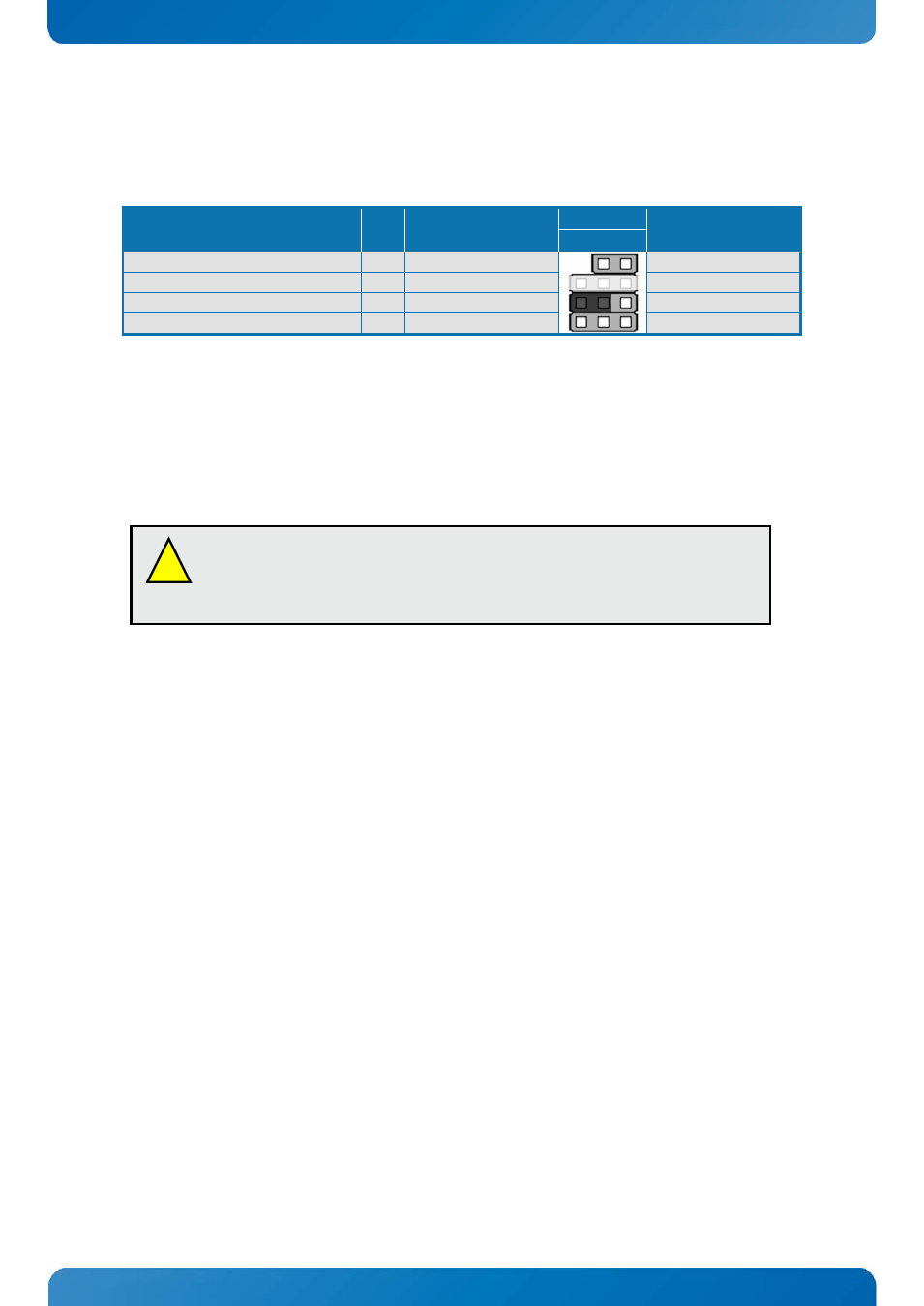
Jumper area (J34, J35, J36, J37)
The KTA70M has a jumper area containing pin connectors 2.54mm pitch, for up to four jumpers, but
normally only one jumper is used (jumper in the J34 pin 2-3 position, as indicated below).
Function
J# Jumper in position
2-3
Pin
Jumper in position
1-2
3 2 1
Always On
J37
-
Always On
(none – connector not mounted) J35
-
-
Clear CMOS
J34
Normal (Default)
Clear CMOS
Audio Short circuit test
J36
Front Left
Front Right
Always On: is PT not supported.
(None): Not mounted on final version of board. Only mounted on Early Field Test versions of KTA70M.
Clear CMOS: is used to erase all customised BIOS settings located in the CMOS RAM storage. If the board has
a booting problem or is unstabile, then Clearing CMOS by moving the Jumper from default position to the
Clear CMOS position for approx. 10 sec. might solve the problem.
Audio Short Circuit Test: is only used in manufacturing test. No jumper should be installed.