1 hot swap, 2 unit computer rs232 management interface, Table 3-21: serial port (rj45) pin assignment – Kontron AT8404 User Manual
Page 52
Hardware Description
39
AT8404 User Guide
www.kontron.com
3.2.1 Hot Swap
The RTM8030 supports hot swapping by using the switch connected to the face plate lower ejector. The inser-
tion or extraction procedure is identical to the ATCA AMC behaviour. The hot swap procedure is controlled by
the RTM's Module Management Controller (MMC).
3.2.1.1
Inserting the RTM8030 into the slot
The presence of the RTM is indicated by one signal. The front blade IPMC recognizes the RTM insertion when
this signal is low. As soon as inserted, the MMC on the RTM turns the blue LED ON and enables the management
power to the RTM. Once the I2C link is working, the IPMC of the front blade accesses the serial EEPROM to re-
trieve FRU data. After knowing the type of RTM inserted, the IPMC negotiates with shelf manager in order to
activate the payload power. After RTM local voltages have been ramped up, the IPMC on the front blade en-
ables the RTM Link.
3.2.1.2
Removing the RTM8030 from the slot
Opening the RTM lower ejector handle indicates to the front blade IPMC that a hot swap action is going to take
place. The IPMC then negotiates the removal with the shelf manager and if it is granted, it proceeds with the
removal process.
The MMC is notified that the RTM blade can be removed. The MMC then activates reset to the RTM blade, dis-
ables the RTM Link and turns off the payload power. When it is safe to remove the RTM blade from the slot, the
MMC turns the Blue / Hot Swap LED on.
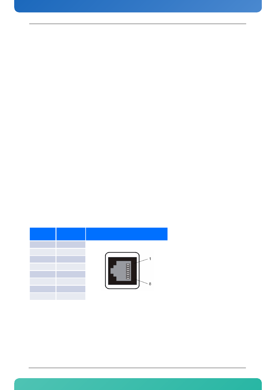
3.2.2 Unit Computer RS232 Management Interface
The Unit Computer's RS232 management interface is implemented as a RJ45 connector. It the lowest one of
the threefold RJ45 connector, labelled with "0". The connector labelled with "1-7" is not in use.
The connector has the following pinning.
Table 3-21: Serial Port (RJ45) Pin Assignment
Pin Num-
ber
Signal
RJ45
1
RTS
2
DTR
3
TXD
4
GND
5
GND
6
RXD
7
DSR
8
CTS