Elecraft XV Transverter Owner's Manual User Manual
Page 9
- 5 -
Refer to the Using Transverters in your K3 Owner’s Manual to
configure the K3 for operation with the transverter:
_ Note the XVn ADR number you have set up for the transverter.
_ Set the maximum output to: L1.00 (1.00 milliwatts).
Refer to the following table and set the DIP switches on the RF PCB
for the XVn address you assigned.
XVn
DIP SWITCH POSITIONS
1 2 3 4
1
ON
OFF OFF
OFF
2
OFF
ON
OFF OFF
3
OFF OFF
ON
OFF
4
OFF OFF
OFF
ON
5
OFF
ON
ON
OFF
6
OFF
ON
OFF
ON
7
OFF OFF
ON
ON
8
OFF
ON
ON
ON
Place 2-pin shorting blocks on the transverter RF PCB jumpers
shown below:
_ JP1: 1-2
_ JP2: 2-3
_ JP3: 1-2
_ JP4: 1-2
_ JP5: 2-3
_ JP6: 2-3
_ JP9: 1-2
Place a shorting block on 2-pin jumper JP8 (near the ON/OFF switch
on the RF PCB) and verify that there is no shorting block on JP7.
Locate front panel PCB 2-pin jumper, JP1, at the end of the socket-
mounted controller IC. Verify that there is no shorting block on this
jumper. (Do not confuse this JP1 with JP1 on the RF PCB.)
Refer to Transverter Control Cable on page 11 to make up a new
transverter control cable or to add connections for the transverter to your
existing cable.
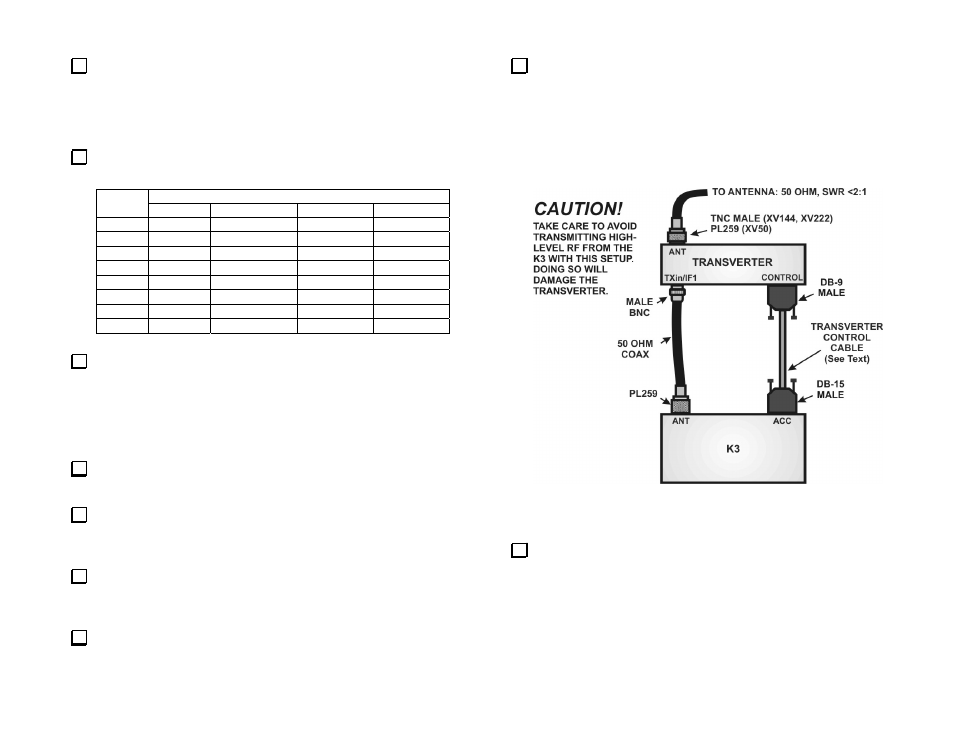
Connect the cables as shown in Figure 1.
Connect a 13.8 VDC, 6 ampere power supply to the transverter using
a cable equipped with an Anderson Powerpole® connector.
Elecraft K3 with No KXV3 Adapter
This setup uses the K3’s antenna port for both the transmit and receive
signal path to the transverter.
Figure 2. Connecting the transverter to an Elecraft K3 Without a
KXV3 Interface.
.
Refer to the Using Transverters in your K3 Owner’s Manual to
configure the K3 for operation with the transverter:
_ Note the XVn ADR number you have set up for the transverter.
_ Set the maximum output to: H5.0 (5 watts).