Daisy-chaining multiple transverters – Elecraft XV Transverter Owner's Manual User Manual
Page 18
- 14 -
Daisy-Chaining Multiple Transverters
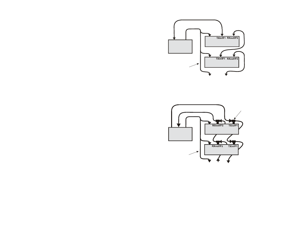
You can “daisy chain” several transverters together as shown in Figure 11
to avoid swapping cables when switching between them.
Relays inside the transverters disconnect the transverters not in use so
they do not load the RF lines.
When using an Elecraft K3 or K2 for the 28 MHz I.F. rig, a multi-wire
control cable is required. See Transverter Control Cable on page 11 for
instructions to prepare the cable. The control cable connects between the
AUX I/O DB-9 connector on the K2 or the ACC DB-15 connector in a
K3 and the CONTROL DB-9 connector on each transverter.
When using a non-Elecraft rig, the two-wire key line is connected in
parallel to the KEY IN RCA connector on each transverter.
The transverter in use is selected as follows:
When using an Elecraft K2 or K3, the desired transverter is
enabled when the transverter band is selected.
When using a non-Elecraft rig for the 28 MHz I.F., the desired
transverter is selected by its front panel ON/OFF switch.
TO ADDITIONAL
TRANSVERTERS
28 MHZ
RIG
CONTROL OR
KEY LINE
(SEE TEXT)
CONTROL OR
KEY LINE
(SEE TEXT)
TX & RX I.F.
TRANSVERTER
TRANSVERTER
TO ADDITIONAL
TRANSVERTERS
28 MHz
RIG
TX I.F.
RX I.F.
BNC
“T” CONNECTORS
TRANSVERTER
TRANSVERTER
COMBINED RECEIVE AND TRANSMIT RF CONNECTIONS
SEPARATE RECEIVE AND TRANSMIT RF CONNECTIONS
Figure 11. Daisy-Chaining Transverters.