Dip switch – Elecraft XV Transverter Owner's Manual User Manual
Page 51
Elecraft
XV
Series
Transverters
Page
C-2
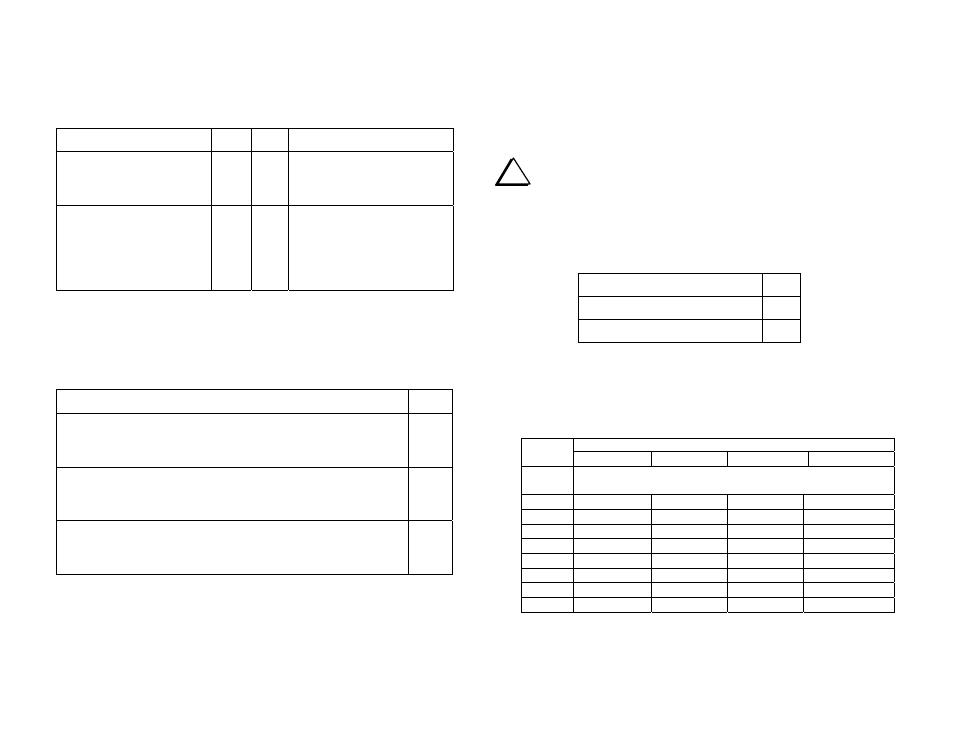
I.F. PORT CONFIGURATION
These jumpers configure the I.F. ports for either separate transmit and
receive RF connections to the 28 MHz rig or common transmit and
receive RF connection to the 28 MHz rig.
Function JP1
JP2
Notes
Single I.F. Port Sharing
Transmit and Receive
2-3 1-2
When single coaxial cable
connects transverter to 28
MHz rig antenna connector.
Separate Transmit and
Receive I.F. Ports
1-2 2-3
When separate coaxial
cables are used for transmit
and receive (e.g. K2 with
K60XV module or K3 with
KXV3 interface).
LOCAL OSCILLATOR POWER CONTROL OPTIONS
These jumpers allow the local oscillator to be left operating at all times
power is applied to the transverter for maximum stability, or to turn it off
to avoid possible interference from the local oscillator on other bands.
Power Option
JP-9
Local oscillator power turns Off when transverter is deselected
at the Elecraft K2 or K3, or when the transverter Power switch
is Off (if the transverter Power switch is enabled).
1-2
Local oscillator power is On whenever transverter power
switch is On (if the transverter Power switch is enabled) even
when the transverter is not selected by the Elecraft K2 or K3.
2-3
Local oscillator power is On whenever +12 volts is applied to
the transverter, regardless of the Power Switch setting or
whether the transverter is selected by the Elecraft K2 or K3.
4-5
TRANSMIT DELAY OPTION
This option allows holding the transverter in transmit mode for up to 200
milliseconds after the 28 MHz rig has switched the KEY line to receive
to avoid timing problems with some rigs. It is not available when using
an Elecraft K2 or K3. The K2 or K3 has the proper timing to work with
the transverter as the fastest-possible speeds.
i
This jumper is located on the front panel board, between the
end of the socket-mounted processor and the side of the transverter.
Do not confuse it with JP1 on the transverter RF board.
These are two-pin jumpers. X indicates a shorting block in place. O
indicates no shorting block.
Function JP1
50 ms T/R delay
O
200 ms T/R delay
X
DIP Switch
The DIP switch on the transverter RF board is used to identify whether
the 28-MHz rig used with the transverter is an Elecraft K2 or K3 and, if
the rig is a K2 or K3, which TRN number (K2) or XVn number (K3) has
been assigned to the transverter.
TRN or
XVN
DIP SWITCH POSITIONS
1 2 3 4
No K2
or K3
ALL SWITCHES OFF
1
ON
OFF OFF OFF
2
OFF
ON
OFF OFF
3
OFF OFF
ON
OFF
4
OFF OFF OFF
ON
5
OFF
ON
ON
OFF
6
OFF
ON
OFF
ON
7
OFF OFF
ON
ON
8
OFF
ON
ON
ON