Elecraft XV Transverter Owner's Manual User Manual
Page 11
- 7 -
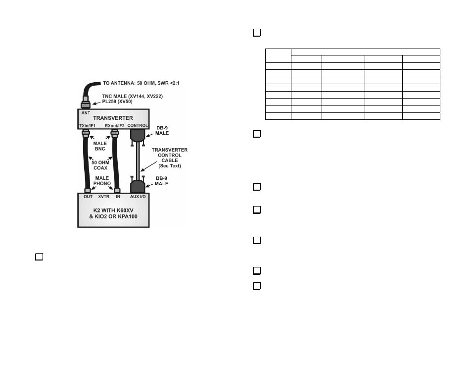
Elecraft K2 with K60XV Adapter
This setup uses the low-level transmit and separate receiver connections
provided by the K60XV Adapter. The K2 must be equipped with an
auxiliary input/output either through a KIO2 interface or the one built into
the KPA100 amplifier.
Figure 3. Connecting the Transverter to an Elecraft K2 with a K60XV
Interface.
Refer to the Transverter Operation section of the Elecraft K60XV
60-M and Transverter Adapter Assembly and Operating Instructions and
use the K2’s MENU commands to configure the K60XV for operation
with the transverter:
_ Note the TRN number you have set up for the transverter.
_ Set the maximum output to: Out L 1.00 (1.00 milliwatts).
Refer to the following table and set the DIP switches on the RF PCB
for the TRN number you assigned.
TRN
DIP SWITCH POSITIONS
1 2 3 4
1
ON
OFF OFF
OFF
2
OFF
ON
OFF OFF
3
OFF OFF
ON
OFF
4
OFF OFF
OFF
ON
5
OFF
ON
ON
OFF
6
OFF
ON
OFF
ON
7
OFF OFF
ON
ON
8
OFF
ON
ON
ON
Place 2-pin shorting blocks on the transverter RF PCB jumpers
shown below:
_ JP1: 1-2
_ JP2: 2-3
_ JP3: 1-2
_ JP4: 1-2
_ JP5: 2-3
_ JP6: 2-3
_ JP9: 1-2
Place a shorting block on 2-pin jumper JP8 (near the ON/OFF switch
on the RF PCB) and verify that there is no shorting block on JP7.
Locate front panel PCB 2-pin jumper, JP1, at the end of the socket-
mounted controller IC. Verify that there is no shorting block on this
jumper. (Do not confuse this JP1 with JP1 on the RF PCB.)
Refer to Transverter Control Cable on page 11 to make up a new
transverter control cable or to add connections for the transverter to your
existing Aux I/O cable.
Connect the cables as shown in Figure 3.
Connect a 13.8 VDC, 6 ampere power supply to the transverter using
a cable equipped with an Anderson Powerpole® connector.