Elecraft XV Transverter Owner's Manual User Manual
Page 32
- 28 -
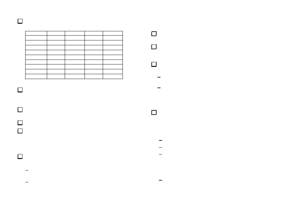
Pre-set the inductors in the transverter as follows. Turns are measured
down from the point where the slug is flush with the top of the coil.
COIL XV50
XV
144
XV222
XV432
L3 N/A*
N/A*
N/A* 5.5
L4 N/A*
N/A*
N/A* 3.5
L5 N/A*
N/A*
N/A* 2.5
L12 0 6 6
N/A*
L13 3 6 6
N/A*
L14 1.5 6 6 N/A*
L15 2 2 2 1
L16 2 2 2 2
L17 2 2 2 0
* Inductor not used on this model.
If you are aligning an XV222, set the slug in inductor L4A even with
the top of the form. This slug will not be adjusted in the following
procedure. L4A is used only in the XV222 transverter.
Connect an RF power meter and dummy load to the transverter ANT
connector.
Verify that the transverter Power switch is off (button out).
If you haven’t already done so, turn to the Installation section
(Page 4) and hook up your transverter to your 28 MHz rig,
Part II – Power Control
Apply power to your 28 MHz rig and verify that the transverter power
control operates as follows:
If you are using a non-Elecraft 28 MHz rig, press the transverter
Power pushbutton in. Verify that the band label lights.
If you are using an Elecraft K2 or K3, confirm that the
transverter band label lights when you select the band assigned to
the transverter on the K2 or K3, and that the band label goes off
when you select any other band. The transverter Power
pushbutton should be inoperative.
Part III - Local Oscillator Level
Verify the proper local oscillator level as follows:
Connect your DMM between a ground test point and TP1 in the
lower right quadrant of the RF PCB.
If you are aligning an XV222, preset the slug in L19 (near the
crystal in the lower right quadrant) so it is about half-way out of the top
of the core.
Apply power to your 28 MHz rig and verify that the transverter
power control operates as follows:
If you are using a non-Elecraft 28 MHz rig, press the transverter
Power pushbutton in. Verify that the band label lights.
If you are using an Elecraft K2 or K3, confirm that the
transverter band label lights when you select the band assigned
to the transverter on the K2 or K3, and that the band label goes
off when you select any other band. The transverter Power
pushbutton should be inoperative.
Verify that the local oscillator voltage levels are as follows. If you
find no reading, make sure you have a 2-pin shorting block on JP9. The
local oscillator is disabled if this shorting block in not installed. See
Local Oscillator Power Control on page 16 to choose the correct
position for the shorting block on JP9.
XV50: 0.8 to 1.2 VDC (No adjustments).
XV144: 1.2 to 1.8 VDC (No adjustments).
XV222: If the voltage is between 1.0 and 1.5 VDC, remove the
slug from the L19. It will not be used. If there is no voltage, or if
it is below 1.0 VDC, screw in the slug while watching for the
point where the voltage stops rising and stop (do not adjust for a
“peak”).
XV432: Adjust L3, L4 and L5 for maximum: The peak voltage
should be between 1.5 and 3.0 VDC (nominally 2.5 VDC).