Elecraft XV Transverter Owner's Manual User Manual
Page 16
- 12 -
Strip of 3/16” (5 mm) of insulation from the black, red and green
wires.
Twist the strands of each wire together. If you are daisy-chaining
cables, twist the ends of leads with like colors together. Tin lightly with
solder.
Solder the wires to the male DB-9 connector supplied with your
transverter as shown in Figure 8.
i
Follow the color codes shown below when wiring the
connector. The same color code is used in the control interface cables
for other Elecraft equipment. A consistent color code will help avoid
mistakes and make troubleshooting easier.
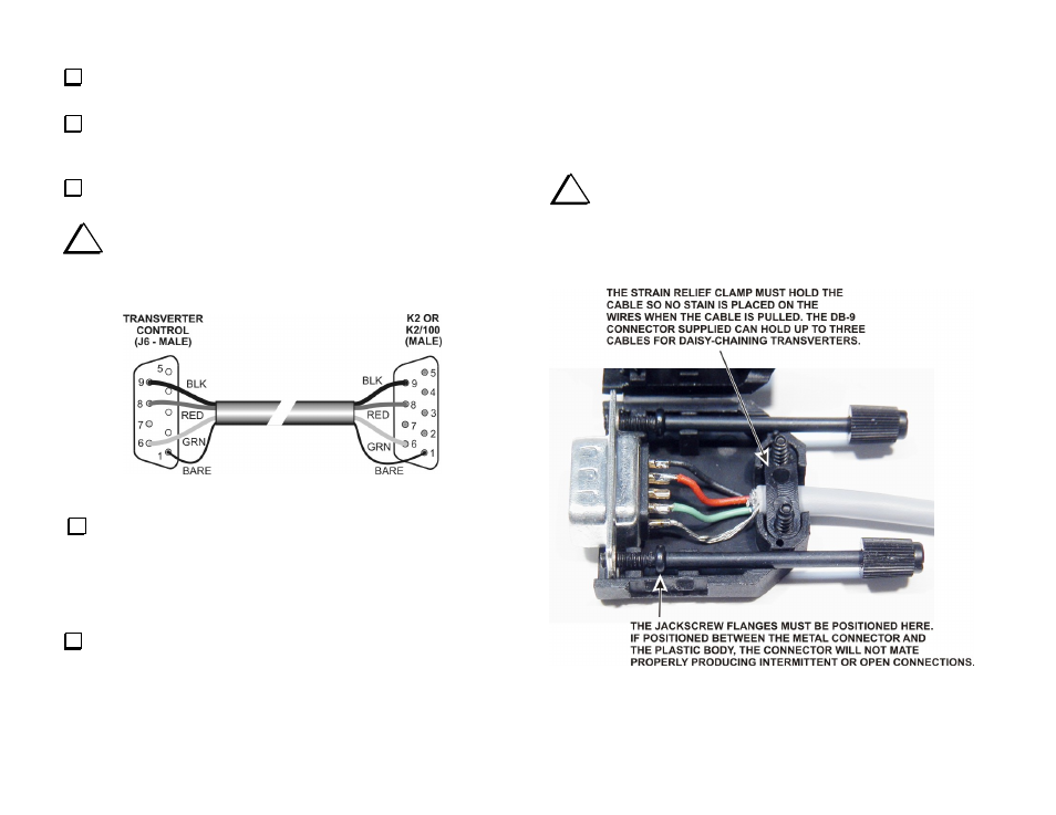
Figure 8. K2 Control Cable Wiring.
If you have not built an RS-232 or control cable to connect other
equipment to your K2, you should have an unused DB-9 male connector
that was supplied with the KI02 or KPA100 kit. In that case, wire the
connector as shown in Figure 8. If you have wired the cable for the K2
and other accessories already, add the transverter extension(s) to it as
shown in Figure 10.
Attach the connector housings (see Figure 9).
This completes your transverter control cable. If, in the future, you
chose to add more transverters, add a KAT100 ATU interface to your
H.F. station, or connect your K2 to a personal computer, you can add
the connections to your existing cable as shown in Figure 10.
Installing the Connector Housing
The connector housing is essential for a reliable, secure cable connection.
A typical DB-9 housing is shown in Figure 9. Attach it to the cable as
shown. Other makes of housings may be somewhat different, but should
provide jack screws to secure it and an effective strain relief to prevent
broken wires.
i
Be especially careful to position the jack screws as shown so
the connectors fully mate when they are tightened. Otherwise you
may find that the connections are intermittent or open even though
the connector is securely mounted to the transverter or rig.
Figure 9. Installing the Connector Housing.