Elecraft XV Transverter Owner's Manual User Manual
Page 15
- 11 -
Transverter Control Cable
Your transverter was supplied with a DB-9 cable connector and a length
of multi-conductor wire for making up the transverter control cable for use
with an Elecraft K3, K2 or K2/100.
Elecraft K3
A male DB-15 connector is provided with your kit to mate with the ACC
connector on the back of your K3. Wire your control cable as follows:
Cut a length of the 4-conductor cable to suit the needs of your station
layout. Keep the cable length as short as practical. A length of 2’ (60 cm)
is recommended. Longer lengths may be used, but you may need to supply
a more heavily-shielded cable to avoid RF interference.
If you are integrating two or more transverters into the station at this
time, cut a length of cable to reach from the first transverter to the next
transverter in a daisy-chain arrangement (see Figure 7).
Remove 1/2” (12 mm) of the jacket from the cable at each end. Be
very careful not to nick the individual wires.
Peel back and cut away the foil shield. Do not cut the bare ground
wire.
Cut the white wire where it exits the jacket. It will not be used.
Strip of 3/16” (5 mm) of insulation from the black, red and green
wires.
Twist the strands of each wire together. If you are daisy-chaining
cables, twist the ends of leads with like colors together. Tin lightly with
solder.
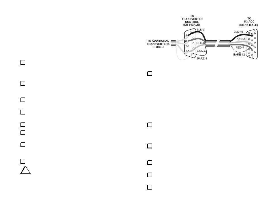
Solder the wires to the connectors as shown in Figure 7.
i
Follow the color codes shown below when wiring the
connector. The same color code is used in the control interface cables
for other Elecraft equipment. Keeping a consistent color code will
help avoid mistakes and make troubleshooting easier.
Figure 7. K3 Control Cable Wiring.
Attach the connector housings (see Figure 9).
Elecraft K2 or K2/100
You will need the DB-9 connector that came with your KIO2 or KPA100
to complete the cable. Follow the procedure below to make up your
control cable.
If you are already using the K2 Aux I/O port to control a KPA100 ATU or
to communicate with your personal computer, you may add the transverter
control cable to the existing cable at the DB-9 connector so you won’t
need to switch connectors when using the transverter (see Figure 10).
Cut a length of the 4-conductor cable to suit the needs of your station
layout. Keep the cable length as short as practical. A length of 2’ (60 cm)
is recommended. Longer lengths may be used, but you may need to supply
a more heavily-shielded cable to avoid RF interference.
If you are integrating two or more transverters into the station at this
time, cut a length of cable to reach from the first transverter to the next
transverter in a daisy-chain arrangement (see Figure 10).
Remove 1/2” (12 mm) of the jacket from the cable at each end. Be
very careful not to nick the individual wires.
Peel back and cut away the foil shield. Do not cut the bare ground
wire.
Cut the white wire where it exits the jacket. It will not be used.