Elecraft XV Transverter Owner's Manual User Manual
Page 14
- 10 -
Non-Elecraft 28 MHz Rig – Single Transmit and Receive
RF Connection
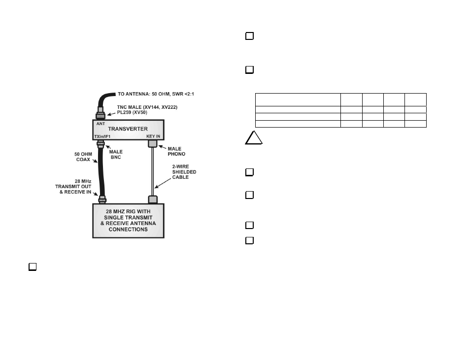
This setup is for any 28 MHz rig with a single RF port for transmit and
receive. The transmitter must be capable of providing a variable RF power
output of up to 1 milliwatt, 251 milliwatts or 5 watts, and provide a key
line that will ground a 5 volt logic level on transmit.
Figure 6. Connecting the Transverter to a Non-Elecraft 28-MHz Rig
with a Single Transmit and Receive RF Path.
On the transverter RF PCB, set all four DIP switches to OFF.
Place 2-pin shorting blocks on transverter RF PCB jumpers shown
below:
_ JP1: 2-3
_ JP2: 1-2
_ JP9: 1-2
From the options below, choose the power output from your 28 MHz
rig that will drive the transverter to full output. Place 2-pin shorting blocks
on the corresponding RF PCB jumpers as shown:
28 MHZ DRIVE LEVEL FOR
FULL TRANSVERTER OUTPUT
JP3 JP4 JP5
JP6
1 milliwatt
1-2
1-2 2-3 2-3
251
milliwatts
1-2 1-2 1-2 1-2
5
watts
2-3 2-3 1-2 1-2
i
Take care not to exceed the maximum power level you set up
the transverter for in the previous step. Doing so may result in
damage to the transverter.
Place a shorting block on 2-pin jumper JP7 (near the ON/OFF switch
on the RF PCB) and verify that there is no shorting block on JP8.
Place a shorting block on front panel PCB 2-pin jumper JP1 at the
end of the socket-mounted controller IC. (Do not confuse this JP1 with
three-pin jumper JP1 on the RF PCB.)
Connect the cables as shown in Figure 6.
Connect a 13.8 VDC, 6 ampere power supply to the transverter using
the cable equipped with an Anderson connector.