Appendix c – jumper and dip switch settings – Elecraft XV Transverter Owner's Manual User Manual
Page 50
Elecraft
XV
Series
Transverters
Page
C-1
Appendix C – Jumper and DIP Switch Settings
Jumpers
The following is a summary of all the jumpers and their functions. The
recommended jumper settings are provided in the Installation instructions
for most station configurations. This summary is provided for general
information and to aid troubleshooting in case your transverter does not
behave as expected.
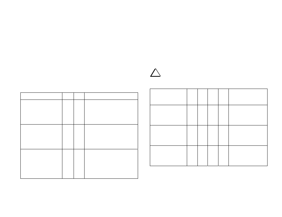
POWER SWITCH OPTIONS
These are two-pin jumpers. X indicates a shorting block in place. O
indicates no shorting block.
Function JP7
JP8
Notes
If 28 MHz Rig is not an
Elecraft K2 or K3
X O
If the transverter is connected
to an Elecraft K2 or K3, be
sure there is no jumper on J7.
Possible damage to the
transverter may result.
Disables the transverter
On/Off pushbutton
when an Elecraft K2 or
K3 is used with the
transverter.
O X
Transverter power is turned On
when the transverter is selected
by the K2 or K3 BAND
switches.
Enables the transverter
On/Off pushbutton
when an Elecraft K2 or
K3 is used with the
transverter.
O O
NOT RECOMMENDED.
This configuration will not
damage the equipment, but
may result in unexpected
behavior of the transverter
power switch.
I.F. POWER CONTROL
The following jumpers are set according to the approximate driving
power from the 28 MHz rig. Fine adjustment is done using Input Atten
Adjust, R22, on the transverter RF board. If you find R22 is difficult to
adjust because it is set too close to one limit of its range, adjust the
jumpers accordingly.
i
Do not exceed the maximum input power from the 28 MHz
rig shown for each jumper configuration. Excessive power may
damage the transverter.
Transmit I.F.
Power from
28 MHz Rig
JP3 JP4
JP5 JP6
Notes
-20 dBm (0.01 mw)
to
0 dBm (1 mw) max.
1-2 1-2 2-3 2-3
JP3 and JP4 bypasses
the fixed attenuator.
JP5 and JP6 enables
amplifier Q6.
Up to +24 dBm
(251 mw) max.
1-2 1-2 1-2 1-2
JP3 and JP4 bypasses
the fixed attenuator.
JP5 and JP6 bypasses
amplifier Q6.
Up to +39 dBm
(8 watts) max.
2-3 2-3 1-2 1-2
JP3 and JP4 enables
the fixed attenuator.
JP5 and JP6 bypasses
amplifier Q6.