Elecraft K144XV Manual User Manual
Page 16
16
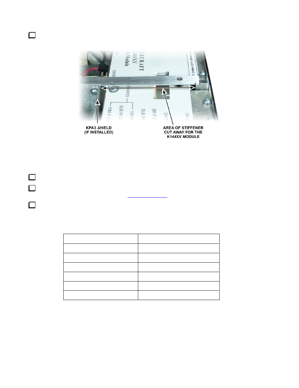
Replace the chassis stiffener using the screws you removed earlier. If your original stiffener lacks the
cutout required for the K144XV as shown in Figure 10, use the stiffener supplied with your K144XV kit.
Figure 10. Chassis Stiffener for K144XV.
Enabling the K144XV Module
The following steps configure your K3 for use with the K144XV option.
Reconnect power to your K3 and turn it on.
Hold CONFIG and note the K3 firmware revision displayed. It must read 4.12 or later. If necessary,
download and install the latest firmware from
www.elecraft.com
before proceeding.
In the CONFIG menu, set the parameters shown below. Note: This table assumes you’re using transverter
band 1 for the K144XV. (XV1). If you already have one or more external transverters connected to the K3, you
can select a different band for the K144XV. For example, if you wish to use band XV2, tap ‘2’ on the numeric
keypad before setting up parameters. When you are finished, tap CONFIG to leave the menu.
Menu Entry (VFO B)
Parameter (VFO A)
XV1 ON
YES
XV1 RF
144
XV1 IF
28
XV1 PWR
L 1.50 (see note 1)
XV1 OFS
0.00
XV1 ADR
Int. Trn0 (see note 2)
NOTES:
1) 1.0 mW is the normal drive level for full output. See Output Power Adjustment on page18for more
information about properly adjusting the drive and output power levels.
2) Setting
ADR
to
Int Trn0
tells the K3 than the internal 2 meter module is being used rather than an
external transverter. This sets up the KXV3A correctly and enables automatic K144XV crystal
switching at the 146-MHz boundary.
Int Trn1
through
Int Trn9
are provided for using the K144XV to
drive higher-frequency transverters (see Using External Transverters with the K144XV on page 20.)