Elecraft K144XV Manual User Manual
Page 13
13
If you have a K3/100, skip this step. If you have a K3/10 with the blank rear panel, replace it as follows:
Install the TMP cable with a BNC connector at one end on the blank panel. Remove the nut and lock
washer (if on the BNC) and thread the cable through the ANT3 hole in the panel from the side with the
ANT3 legend, then replace the lock washer and nut. Tighten the nut to hold the BNC securely.
Install the blank panel on the K3 oriented so the ANT3 connector is on the left end near the SO-239
ANT1 and (if installed) ANT2 connectors. Route the TMP end of the cable over near the KIO3 board. It
will be connected to the K144XV module later.
Installing the K144XV Module in the K3
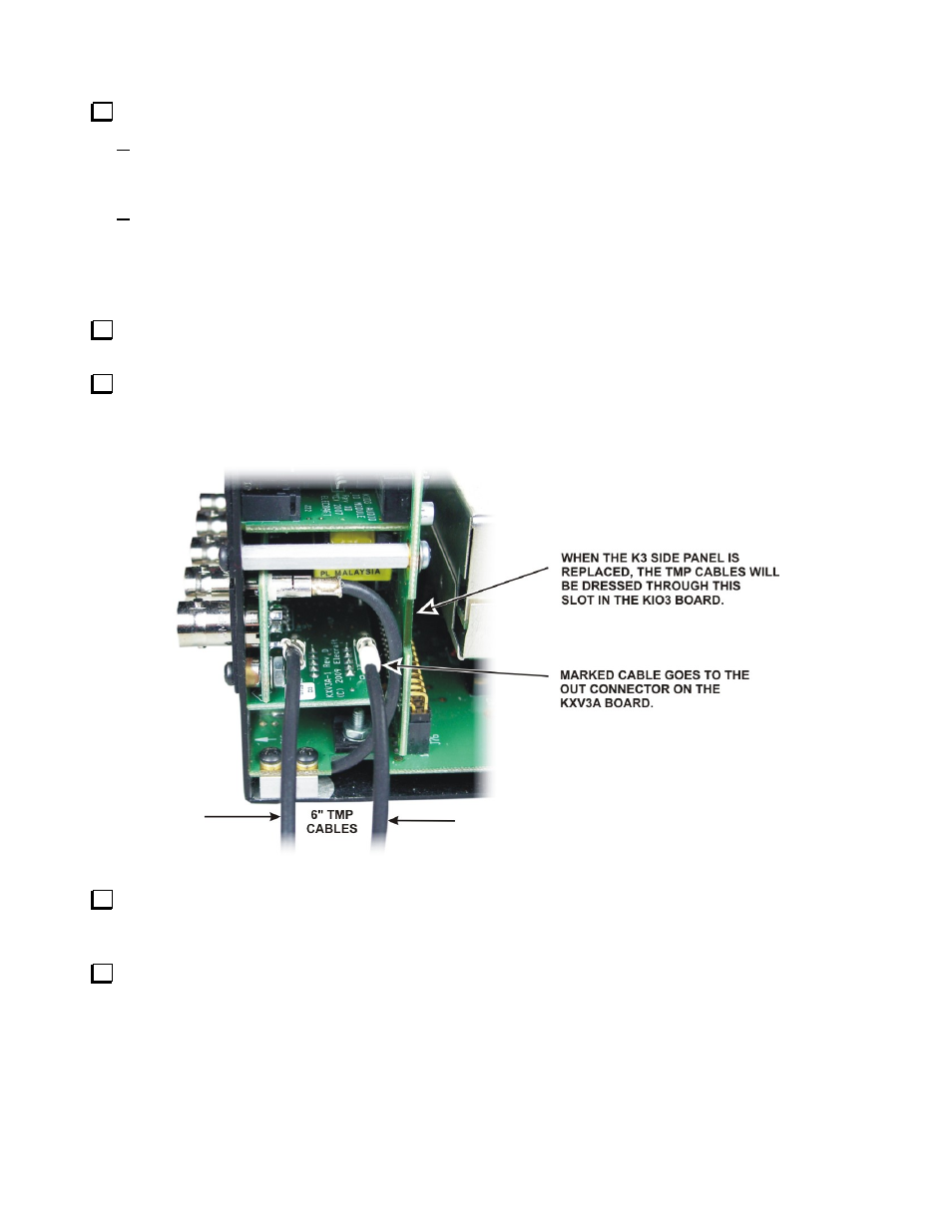
Locate the two 6” (15.2 cm) TMP cables. One is marked near the connector at each end. Typically the
mark will be a colored band. White is used in this manual so it will show up clearly in the photographs.
Plug the cables into the two TMP connectors on the KXV3A board (see Figure 6). Note the connectors on
the KXV3A are marked IN and OUT. Be sure the marked TMP cable is in the OUT connector on the KXV3A.
The purpose of the marked cable is to positively identify the cable after the K3 side is replaced and you can no
longer see the KXV3A board. Be sure the connectors are fully seated.
Figure 6. Attaching TMP cables to the KXV3A Interface Board.
Mount the left side panel on the K3. Be sure you use the side panel equipped with the holes for mounting
the K144XV module (see Figure 2). Route the two TMP cables from the KXV3 through the slot in the KIO3
board (see Figure 6) so they are not pinched between the side panel and the KIO3 circuit board.
Mount the K144XV module on the side panel using three 6-32 1/4” (6.4 mm) black flat head screws as
shown in Figure 7. Be sure you don’t trap any of the TMP cables underneath the module.