Elecraft K144XV Manual User Manual
Page 10
10
Remove the K3’s left side panel (the side with the handle). Check the panel to determine whether it has the
three mounting holes for the K144XV module shown in Figure 2. The three mounting holes may have screws in
them:
If the side panel does not have the mounting holes, move the handle onto the new side panel with the
required holes furnished with your K144XV kit.
If the side panel has the three holes, remove the 6-32 flat head screws filling them.
Do not reinstall the side panel until instructed to do so later.
Figure 2. Left Side Panel with Holes for K144XV Module.
Locate the KXV3A board visible in the lower left corner of the K3 looking in from the open side (see
Figure 6 on page 13) and verify the two coaxial TMP connectors are present. If not, your K3 has an older KXV3
board that must be replaced. Turn to your KXV3A manual and install the new board now. If your K3 is
equipped with the KRX3 subreceiver the KXV3A manual will instruct you to remove it. If so, do not replace the
KRX3 subreceiver module until instructed to do so later.
K144XV Power Connector
Check to see if the one-pin power connector is already installed on the K3’s RF board (see Figure 4). If so,
skip the following steps and go directly to Installing the ANT3 Connector on page 11.
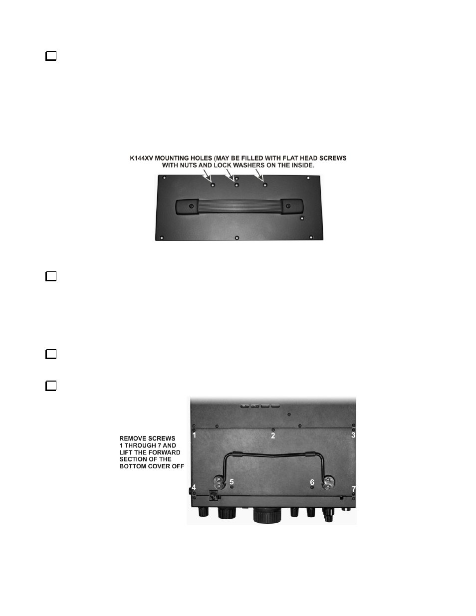
Remove the forward section of the K3’s bottom cover as shown in Figure 3.
Figure 3. Removing K3 Bottom Cover.