Elecraft K144XV Manual User Manual
Page 11
11
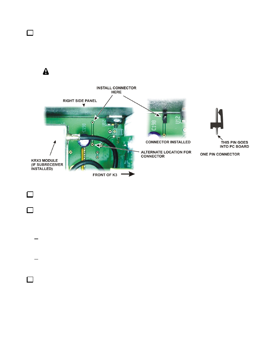
Solder the male half of the one –pin connector to the via (copper plated hole through the board) near the
front right area of the K3 main RF board just behind the front panel shield as shown in Figure 4. That via may
be occupied on some K3’s. If so, use the alternate location shown. Mounting the connector may be done by
standing the K3 on its left side and inserting the connector in the hole in the pc board. Carefully solder the pin to
the copper via on the bottom. If necessary, you can straighten the connector after soldering by pressing down on
the shoulder with your finger while reheating the solder on the bottom.
Limit your soldering time to 2 or 3 seconds maximum to avoid melting the connector. If
you want to adjust the its position after soldering, let connector cool before reheating the
solder.
Figure 4. Installing the One-Pin Power Connector on the K3 RF Board.
Replace the forward section of the K3 bottom cover. Be sure to replace and tighten all seven screws shown
in Figure 3.
If your K3 is not equipped with the KRX3 Subreceiver, skip this step and go directly to Installing the ANT3
Connector below. If you removed the subreceiver earlier, turn to your KRX3 Subreceiver Installation and
Operation manual, Installing the KRX3 Subreceiver Module section to replace the KRX3 module. Be especially
careful to do the following as described in that procedure:
Be sure the cover on battery BT1 on the K3 RF board is in place. The cover is essential to avoid
shorting the battery. The outer rim of the battery is the positive terminal, and may come in contact with
the grounded bottom of the KRX3 enclosure if the cover is not in place.
Be sure all the TMP cables are properly connected and routed as shown in the KRX3 manual.
Installing the ANT3 Connector
Remove the rear fan panel (if you have a K3/100) or the blank rear panel (if you have a K3/10) by removing
the four corner screws. If you have a K3/100, unplug the fans and the circuit breaker. The wires to the circuit
breaker have connectors that pull off of the spade terminals on the back of the breaker. They may be tight, but
will come off with a little wiggling.